Gigabyte GA-H110M-DS2 DDR3 User Manual - Page 15
SATA3 0/1/2/3 SATA 6Gb/s Connectors, F_PANEL Front Panel Header, SPEAK, PLED/PWR_LED
 |
View all Gigabyte GA-H110M-DS2 DDR3 manuals
Add to My Manuals
Save this manual to your list of manuals |
Page 15 highlights
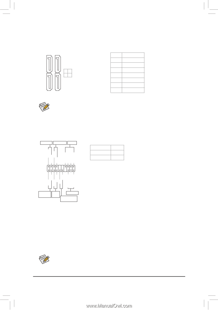
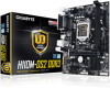
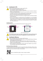
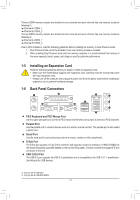
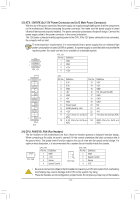
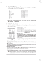
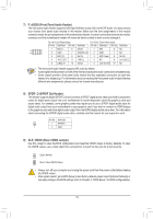
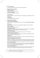
1 23 1 1 23 1 SS 1 S 1 23 1 23 1 5) SATA3 0/1/2/3 (SATA 6Gb/s Connectors) The SATA connectors conform to SATA 6Gb/s standard and are compatible with SATA 3Gb/s and SATA 1.5Gb/s standard. Each SATA connector supports a single SATA device. 77 SATA3 32 10 11 Pin No. 1 2 3 4 5 6 7 Definition GND TXP TXN GND RXN RXP GND To enable hot-plugging for the SATA ports, refer to Chapter 2, "BIOS Setup," "Peripherals\SATA Configuration," for more information. 6) F_PANEL (Front Panel Header) Connect the power switch, reset switch, speaker, chassis intrusion switch/sensor and system status indicator on the chassis to this header according to the pin assignments below. Note the positive and negative pins before connecting the cables. Power LED Power Switch Speaker •• PLED/PWR_LED (Power LED): System Status LED Connects to the power status indicator PLED+ PLED- PW+ PWSPEAK+ NC NC SPEAK- S0 On S3/S4/S5 Off on the chassis front panel. The LED is on when the system is operating. The LED is off when the system is in S3/S4 sleep state F_ 2 1 20 F_ 19 •• PW (Power Switch): or powered off (S5). S S U 123 HD+ HD- RESRES+ CICI+ PWR_LED+ PWR_LEDPWR_LED- Connects to the power switch on the chassis front panel. You may configure the way to turn off your system using the power switch (refer to Chapter 2, "BIOS Setup," "Power Management," for more information). •• SPEAK (Speaker): Hard Drive Reset Activity LED Switch Power LED Chassis Intrusion Header Connects to the speaker on the chassis front panel. The system reports system startup status by issuing a beep code. One single short beep will be heard if no problem is detected at system startup. •• HD (Hard Drive Activity LED): Connects to the hard drive activity LED on the chassis front panel. The LED is on when the hard drive is reading or writing data. •• RES (Reset Switch): _S Connects to the reset switch on the chassis front panel. Press the reset switch to restart the computer if the computer freezes and fails to perform a normal restart. •• CI (Chassis Intrusion Header): Connects to the chassis intrusion switch/se_nsor on the chassis that can detect if the cBhaSs_sis cover has been removed. This function requires a chassis wiBth a chassis intrusion switch/sensor. B •• NC: No connection. The front panel design may differ by chassis. A front panel module mainly consists of power switch, reset switch, power LED, hard drive activity LED, speaker and etc. When connecting your chassis front panel module to this headSerB,_make sure the wire assignments and the pin assignments are matched correctly. B - 15 - _S S_ _ B
-
 1
1 -
2
-
3
-
4
-
5
-
6
-
7
-
8
-
9
-
 10
10 -
 11
11 -
 12
12 -
 13
13 -
 14
14 -
 15
15 -
 16
16 -
 17
17 -
 18
18 -
 19
19 -
 20
20 -
21
-
22
-
23
-
24
-
25
-
26
-
27
-
28
-
29
-
30
-
31
-
32
-
33
-
34
-
35
-
36
-
37
-
38
 |
 |