Gigabyte GA-H110M-Gaming 3 User Manual - Page 14
SATA3 0/1/2/3 SATA 6Gb/s Connectors, F_USB30 USB 3.0/2.0 Header, F_USB1/F_USB2 USB 2.0/1.1 Headers
 |
View all Gigabyte GA-H110M-Gaming 3 manuals
Add to My Manuals
Save this manual to your list of manuals |
Page 14 highlights
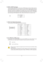
5) SATA3 0/1/2/3 (SATA 6Gb/s Connectors) The SATA connectors conform to SATA 6Gb/s standard and are compatible with SATA 3Gb/s and SATA 1.5Gb/s standard. Each SATA connector supports a single SATA device. 77 SATA3 32 10 11 Pin No. 1 2 3 4 5 6 7 Definition GND TXP TXN GND RXN RXP GND To enable hot-plugging for the SATA ports, refer to Chapter 2, "BIOS Setup," "Peripherals\SATA Configuration," for more information. F_USB30 6) F_USB30 (USB 3.0/2.0FH_ eUader) F_ The header conforms to USB 3.0/2.0 specification and each header can provide two USB ports. For purchasing the optional 3.5" front panel that provides two USB 3.0/2.0 ports, please contact the local dealer. Pin No. Definition Pin No. Definition 1 VBUS 11 D2+ 2 SSRX1- 12 D2- 20 1 3 SSRX1+ 13 GND 4 GND 14 SSTX2+ 5 SSTX1- 15 SSTX2- B_ 11 10 6 SSTX1+ 7 GND 8 D19 D1+ B1S6S GND 17 SSRX2+ 1 18 SSRX2- 19 VBUS _S 10 NC 20 No Pin 1 23 1 1 23 1 1 23 1 7) F_USB1/F_USB2 (USB 2.0/1.1 Headers) S The headers conform to USB 2.0/1.1 specification. Each USB header can provide two USB ports via an optional USB bracket. For purchasing the optional USB bracket, please contact the local dealer. 9 1 10 2 Pin No. S1 2 3 4 5 Definition Power (5V) Power (5V) USB DXUSB DYUSB DX+ 1 23 Pin No. Definition 6 USB DY+ 7 GND 8 GND 9 No Pin 10 NC •• Do not plug the IEEE 1394 bracket (2x5-pin) cable into the USB 2.0/1.1 header. •• Prior to installing the USB bracket, be sure to turn off your computer and unplug the power cord from the power outlet to prevent damage to the USB bracket. S3 B S S S- 14 - U __ 3 F S_ SF _
-
 1
1 -
2
-
3
-
4
-
5
-
6
-
7
-
8
-
 9
9 -
 10
10 -
 11
11 -
 12
12 -
 13
13 -
 14
14 -
 15
15 -
 16
16 -
 17
17 -
 18
18 -
 19
19 -
20
-
21
-
22
-
23
-
24
-
25
-
26
-
27
-
28
-
29
-
30
-
31
-
32
-
33
-
34
-
35
-
36
-
37
-
38
 |
 |
