Gigabyte GA-H110M-S2V DDR3 User Manual - Page 17
SPDIF_O S/PDIF Out Header, F_AUDIO Front Panel Audio Header, SPEAKER Speaker Header, wire assignments
 |
View all Gigabyte GA-H110M-S2V DDR3 manuals
Add to My Manuals
Save this manual to your list of manuals |
Page 17 highlights
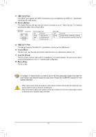
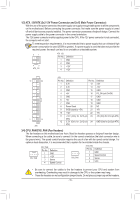
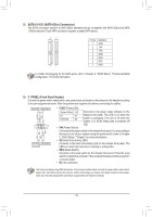
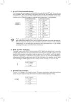
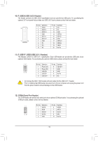
7) F_AUDIO (Front Panel Audio Header) The front panel audio header supports Intel High Definition audio (HD) and AC'97 audio. You may connect your chassis front panel audio module to this header. Make sure the wire assignments of the module connector match the pin assignments of the motherboard header. Incorrect connection between the module connector and the motherboard header will make the device unable to work or even damage it. For HD Front Panel Audio: For AC'97 Front Panel Audio: Pin No. Definition Pin No. Definition 1 MIC2_L 1 MIC 9 1 10 2 2 GND 3 MIC2_R 2 GND 3 MIC Power 4 -ACZ_DET 4 NC 5 LINE2_R 5 Line Out (R) 6 Sense 6 NC 7 FAUDIO_JD 7 NC 8 No Pin 8 No Pin 9 LINE2_L 9 Line Out (L) 10 Sense 10 NC •• The front panel audio header supports HD audio by default. •• Audio signals will be present on both of the front and back panel audio connections simultaneously. •• Some chassis provide a front panel audio module that has separated connectors on each wire instead of a single plug. For information about connecting the front panel audio module that has different wire assignments, please contact the chassis manufacturer. 8) SPDIF_O (S/PDIF Out Header) This header supports digital S/PDIF Out and connects a S/PDIF digital audio cable (provided by expansion cards) for digital audio output from your motherboard to certain expansion cards like graphics cards and sound cards. For example, some graphics cards may require you to use a S/PDIF digital audio cable for digital audio output from your motherboard to your graphics card if you wish to connect an HDMI display to the graphics card and have digital audio output from the HDMI display at the same time. For information about connecting the S/PDIF digital audio cable, carefully read the manual for your expansion card. Pin No. Definition 1 SPDIFO 1 2 GND 9) SPEAKER (Speaker Header) Connects to the speaker on the chassis front panel. The system reports system startup status by issuing a beep code. One single short beep will be heard if no problem is detected at system startup. Pin No. Definition 1 1 VCC 2 NC 3 NC 4 SPK- - 17 -
-
 1
1 -
2
-
3
-
4
-
5
-
6
-
7
-
8
-
9
-
10
-
11
-
 12
12 -
 13
13 -
 14
14 -
 15
15 -
 16
16 -
 17
17 -
 18
18 -
 19
19 -
 20
20 -
 21
21 -
 22
22 -
23
-
24
-
25
-
26
-
27
-
28
-
29
-
30
-
31
-
32
-
33
-
34
-
35
-
36
-
37
-
38
-
39
 |
 |
