Gigabyte GA-H270M-D3H Users Manual - Page 14
SATA EXPRESS SATA Express Connectors, SATA3 0/1/2/3/4/5 SATA 6Gb/s Connectors
 |
View all Gigabyte GA-H270M-D3H manuals
Add to My Manuals
Save this manual to your list of manuals |
Page 14 highlights
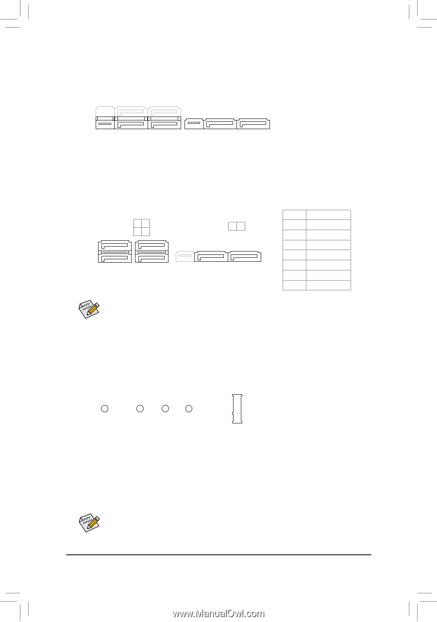
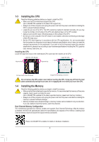
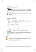
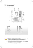
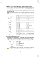
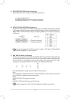
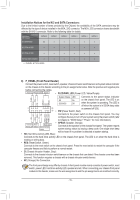
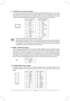
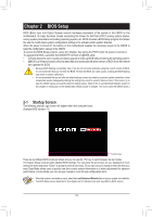
_ B S B_ B _S S_ _ B _U _ B F_USB3 F B S_ B B_ S _S _ B_ S _S 5) SATAS EX_PRESS (SATA Express Connectors) S S Each SATA Express connector supports a single SATA Express device. S_ S_ _ _ _ _ 6) SATA3 0/1/2/3/4/5 (SATA 6Gb/s CoFnnectors) The SATA connectors conform to SATA 6Gb/s standard and are compatible with SATA 3Gb/s and SATA 1.5GbS/s st_andard. Each SATA connector supports a single SATA device. The Intel® Chipset supports RAID 0, RAID 1, RAID 5, and RAID 10. Refer to Chapter 3, "Configuring a RAID Set," for instructions on configuring a RAID array. SATA3 5 G.QBOFM 4 S G_U._0QBOFM SATA3 3 B_ 2 10 Pin No. Definition 1 GND 2 TXP B_ USB 0_ B 7 1 7 1 3 TXN 7 1 4 GND 5 RXN _F 6 RXP 7 GNDB_ U To enable B_ hot-plugging for the SATA ports, refer to Chapter 2U,S"BB0IO_ BS Setup," "Peripherals\SATA B_ And RST Configuration," for more information. U B_ USB 0_ B _0 F 7) M2A_32G (M.2 Socket 3 Connector) The M.2 connector supports M.2 SATA SSDs and M.2 PCIe SSDs and support RAID configuration through the Intel® Chipset. Please note that an M.2 PCIe SSD cannot be used to create a RAID set either with an M.2 SATA SSD or a SATA hard drive and can only be used to build a RAID set with UEFI. Refer to Chapter 3, "Configuring a RAID Set," for instructions on configuring a RAID array. 110 80 60 42 Follow the steps below to correctly install an M.2 SSD in the M.2 connector. Step 1: Use a screw driver to unfasten the screw and nut from the motherboard. Locate the proper mounting hole for the M.2 SSD to be installed and then screw the nut first. Step 2: Slide the M.2 SSD into the connector at an angle. Step 3: Press the M.2 SSD down and then secure it with the screw. Select the proper hole for the M.2 SSD to be installed and refasten the screw and nut. - 14 -
-
 1
1 -
2
-
3
-
4
-
5
-
6
-
7
-
8
-
 9
9 -
 10
10 -
 11
11 -
 12
12 -
 13
13 -
 14
14 -
 15
15 -
 16
16 -
 17
17 -
 18
18 -
 19
19 -
20
-
21
-
22
-
23
-
24
-
25
-
26
-
27
-
28
-
29
-
30
-
31
-
32
-
33
-
34
-
35
-
36
-
37
-
38
-
39
-
40
-
41
-
42
-
43
-
44
 |
 |