Gigabyte GA-H61M-USB3H Manual - Page 14
F_AUDIO Front Panel Audio Header, F_USB1/2 USB 2.0/1.1 Headers - bios
 |
View all Gigabyte GA-H61M-USB3H manuals
Add to My Manuals
Save this manual to your list of manuals |
Page 14 highlights
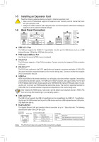
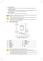
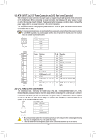
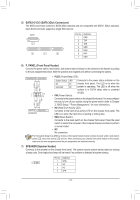
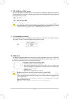
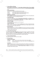
B ( P F_PANEL (H61M-D2) F_PANEL(NH) 8) F_AUDIO (Front Panel Audio Header) The front panel audio header supports Intel High Definition audio (HD) and AC'97 audio. You may connect your chassis front panel audio module to this header. Make sure the wire assignments of the module CLR_CMOS CI DIS_ME GP15_CPT (GA-IVB) XDP_CPU XDP_PCH (GA-IVB) SMB_CPT (GA-IVB) (GA-IVB) ACPI_CPT connector match the pin assignments of the motherboard header. Incorrect connection between the module connector and the motherboard header will make the device unable to work or even damage it. For HD Front Panel Audio: For AC'97 Front Panel Audio: Pin No. Definition Pin No. Definition 9 1 10 2 1 MIC2_L 2 GND 1 MIC 2 GND 3 MIC2_R 3 MIC Power 4 -ACZ_DET 4 NC 5 LINE2_R 5 Line Out (R) 6 GND 6 NC 7 FAUDIO_JD 7 NC 8 No Pin 8 No Pin 9 LINE2_L 9 Line Out (L) 10 GND 10 NC BIOS Switcher (X58A-OC) 1 M_SATA BIOS Switcher (SW4) DIP 1 23 PCIe power connector (SATA)(X58A-OC) •• The front panel audio header supports HD audio by default. •• Audio signals will be present on both of the front and back panel audio connections simultaneously. •• Some chassis provide a front panel audio module that has separated connectors on each wire instead of a single plug. For information about connecting the front panel audio module that has different wire assignments, please contact the chassis manufactureDr.IP PWM Switch (X58A-OC) DIP 1 23 1 DIP 1 23 1 9) F_USB1/2 (USB 2.0/1.1 Headers) 1 2 3 The headers conform1 to USB 2.0/1.1 specification. Each USB header can provide two USB ports via an optional USB bracket. For purchasing the optional USB bracket, please contact the local dealer. Pin No. Definition Pin No. Definition 9 1 10 2 1 Power (5V) 2 Power (5V) 6 USB DY+ 7 GND 3 USB DX- 8 GND 4 USB DY- 9 No Pin 5 USB DX+ 10 NC Voltage measurement module(X58A-OC) 10) F_USB30 (USB 3.0/2.0 Header) The header conforms to USB 3.0/2.0 specification and can provide two USB ports. For purchasing the optional 3.5" front panel that provides two USB 3.0/2.0 ports, please contact the local dealer. DB_PORT Voltage measurement points(G1.Sniper 3) Pin No. Definition Pin No. Definition 1 VBUS 11 D2+ 1 10 2 SSRX1- 12 D2- 3 SSRX1+ 13 GND 4 GND 14 SSTX2+ 20 11 5 SSTX1- 15 SSTX2- 6 SSTX1+ 16 GND 7 GND 17 SSRX2+ 8 D1- 18 SSRX2- 9 D1+ 19 VBUS 10 NC 20 No Pin F_AUDIO(H) F_USB30 TPM w/housing •• Do not plug the IEEE 1394 bracket (2x5-pin) cable into the USB header. •• Prior to installing the USB bracket, be sure to turn off your computer and unplug the power cord from the power outlet to prevent damage to the USB bracket. - 14 -
-
 1
1 -
2
-
3
-
4
-
5
-
6
-
7
-
8
-
 9
9 -
 10
10 -
 11
11 -
 12
12 -
 13
13 -
 14
14 -
 15
15 -
 16
16 -
 17
17 -
 18
18 -
 19
19 -
20
-
21
-
22
-
23
-
24
-
25
-
26
-
27
-
28
-
29
-
30
-
31
-
32
 |
 |