Gigabyte GA-IMB410M User Manual - Page 14
SATA3 0/1/2/3 SATA 6Gb/s Connectors, M2A_SB M.2 Socket 3 Connector
 |
View all Gigabyte GA-IMB410M manuals
Add to My Manuals
Save this manual to your list of manuals |
Page 14 highlights
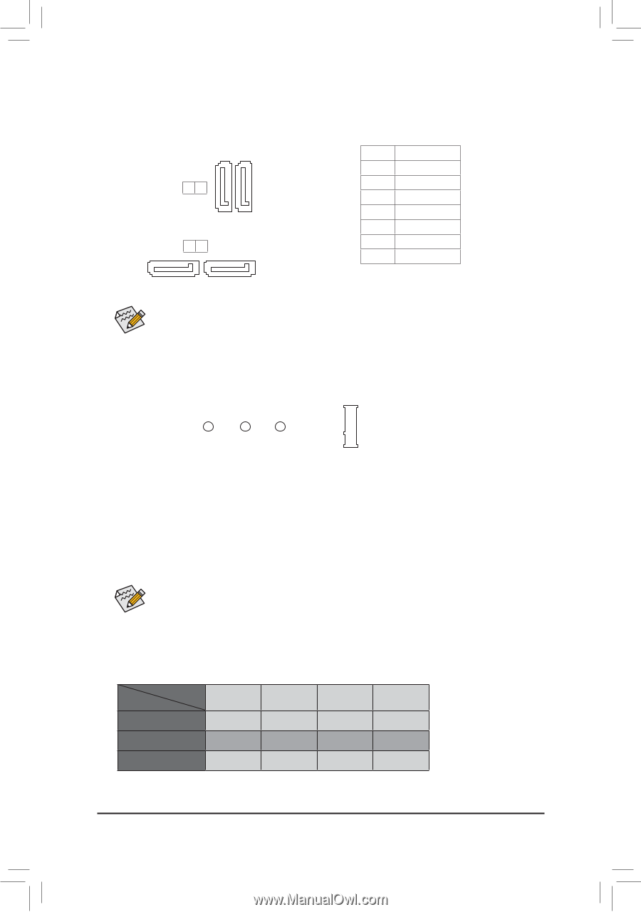
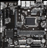
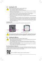
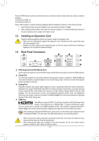
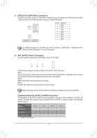
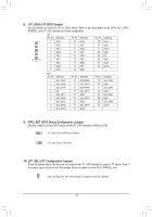
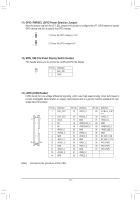
S_ _ B _U _ B F_USB3 F _ DEBUG PORTF DEBUG PORT 5) SATA3 0/1/2/3 (SATA 6Gb/s Connectors) The SATA connectors conform to SATA 6Gb/s standard and are compatible with SATA 3Gb/s and SATA 1.5Gb/s standard. Each SATA connector supports a single SATA device. 11 _0 SATA3 01 S_ 77 SATA3 _F 32 1 7 Pin No. 1 2 3 4 5 6 7 Definition GND TXP TXN GND RXN RXP GND DEBUG PORT DEBUG PORT To enable hot-plugging for the_ 0SATAF ports, refer to Chapter 2, "BIOS Setup," "Settings\IO Ports\ SATA And RST Configuration," for more information. 6) M2A_SB (M.2 Socket 3 Connector) The M.2 connector supports M.2 SATA SSDs and M.2 PCIe SSDs. 80 60 42 Follow the steps below to correctly install an M.2 SSD in the M.2 connector. Step 1: Use a screw driver to unfasten the screw and standoff from the motherboard. Locate the proper mounting hole for the M.2 SSD to be installed and then screw the standoff first. Step 2: Slide the M.2 SSD into the conne_c3tor at aUn angle. Step 3: Press the M.2 SSD down and then secure it with the screw. Select the proper hole for the M.2 SSD to be installed and refasten the screw and standoff. 3 Installation Notices for the M.2 and SATA Connectors: The availability of the SATA connectors may be affected by the type of device installed in the M2A_SB sockets. The M2A_SB connector shares bandwidth with the SATA3 3 connector. Refer to the following table for details. Type of M.2 SSD Connector M.2 SATA SSD SATA3 0 a SATA3 1 a SATA3 2 a SATA3 3 r M.2 PCIe SSD a a a a No M.2 SSD Installed a a a a a: Available, r: Not available - 14 -
-
 1
1 -
2
-
3
-
4
-
5
-
6
-
7
-
8
-
 9
9 -
 10
10 -
 11
11 -
 12
12 -
 13
13 -
 14
14 -
 15
15 -
 16
16 -
 17
17 -
 18
18 -
 19
19 -
20
-
21
-
22
-
23
-
24
-
25
-
26
-
27
-
28
-
29
-
30
-
31
-
32
-
33
-
34
-
35
-
36
-
37
 |
 |