Gigabyte GA-MA790FXT-UD5P Manual
Gigabyte GA-MA790FXT-UD5P Manual
 |
View all Gigabyte GA-MA790FXT-UD5P manuals
Add to My Manuals
Save this manual to your list of manuals |
Gigabyte GA-MA790FXT-UD5P manual content summary:
- Gigabyte GA-MA790FXT-UD5P | Manual - Page 1
GA-MA790FXT-UD5P AM3 socket motherboard for AMD PhenomTM II X3 processor/AMD PhenomTM II X4 processor User's Manual Rev. 1001 12ME-MA79T5P-1001R - Gigabyte GA-MA790FXT-UD5P | Manual - Page 2
Motherboard GA-MA790FXT-UD5P Jan. 22, 2009 Motherboard GA-MA790FXT-UD5P Jan. 22, 2009 - Gigabyte GA-MA790FXT-UD5P | Manual - Page 3
, read the Quick Installation Guide included with the product. For detailed product information, carefully read the User's Manual. For instructions on how to use GIGABYTE's unique features, read or download the information on/from the Support\Motherboard\Technology Guide page on our website - Gigabyte GA-MA790FXT-UD5P | Manual - Page 4
...6 GA-MA790FXT-UD5P Motherboard Layout 7 Block Diagram...8 Chapter 1 Hardware Installation 9 1-1 Installation Precautions 9 1-2 Product Specifications 10 1-3 Installing the CPU and CPU Cooler 13 1-3-1 Installing the CPU 13 1-3-2 Installing the CPU Cooler 15 1-4 Installing the Memory 16 - Gigabyte GA-MA790FXT-UD5P | Manual - Page 5
Chapter 3 Drivers Installation 63 3-1 Installing Chipset Drivers 63 3-2 Application Software 64 3-3 Technical Manuals 64 3-4 Contact ...65 3-5 System ...65 3-6 Download Center 66 Chapter 4 Unique Features 67 4-1 Xpress Recovery2 67 4-2 BIOS Update Utilities 70 4-2-1 Updating the BIOS with - Gigabyte GA-MA790FXT-UD5P | Manual - Page 6
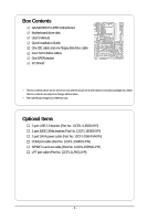
Box Contents GA-MA790FXT-UD5P motherboard Motherboard driver disk User's Manual Quick Installation Guide One IDE cable and one floppy disk drive cable Four SATA 3Gb/s cables One SATA bracket I/O Shield • The box contents above are for reference only - Gigabyte GA-MA790FXT-UD5P | Manual - Page 7
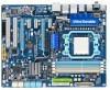
1394_1 KB_MS ATX_12V_2X4 CPU_FAN ATX Socket AM3 USB LAN1 PW_SW RST_SW PWR_FAN USB LAN2 AUDIO F_AUDIO RTL 8111DL PCIEX1_1 NB_FAN RTL PCIEX16_1 8111DL PCIEX1_2 CD_IN PCIEX1_3 CODEC SPDIF_IO PCIEX16_2 CI PCI1 IT8720 PCI2 COM AMD 790FX GA-MA790FXT-UD5P BATTERY CLR_CMOS TSB43AB23 - Gigabyte GA-MA790FXT-UD5P | Manual - Page 8
Diagram 2 PCIe x16 AMD Socket AM3 CPU CPU CLK+/-(200 MHz) DDR3 1666(O.C.)1333/1066 MHz DIMM PCIe CLK (100 MHz) PCI Express x16 Hyper Transport 3.0 Dual Channel Memory LAN2 LAN1 3 PCI Express x1 RJ45 RJ45 RTL RTL PCIe CLK 8111DL 8111DL (100 MHz) x1 x1 x1 x1 x1 AMD 790FX PCI Express Bus - Gigabyte GA-MA790FXT-UD5P | Manual - Page 9
, CPU or memory. If you do not have an ESD wrist strap, keep your hands dry and first touch a metal object to eliminate static electricity. • Prior to installing the motherboard, please have it on top of an antistatic pad or within an electrostatic shielding container. • Before unplugging the - Gigabyte GA-MA790FXT-UD5P | Manual - Page 10
USB Support for Socket AM3 processors: AMD PhenomTM II X3 processor/AMD PhenomTM II X4 processor (Go to GIGABYTE's website for the latest CPU support list.) 5200/2000 MT/s North Bridge: AMD 790FX South Bridge: AMD SB750 4 x 1.5V DDR3 DIMM sockets supporting up to 16 GB of system memory (Note - Gigabyte GA-MA790FXT-UD5P | Manual - Page 11
Monitor System voltage detection CPU/System temperature detection CPU/System/Power fan speed detection CPU overheating warning CPU/System fan fail warning CPU/System fan speed control (Note 4) BIOS 2 x 8 Mbit flash Use of licensed AWARD BIOS Support for DualBIOSTM PnP - Gigabyte GA-MA790FXT-UD5P | Manual - Page 12
Hard Drive(s)," for how to enable the Smart Backup function.) (Note 4) Whether the CPU/system fan speed control function is supported will depend on the CPU/ system cooler you install. (Note 5) Available functions in EasyTune may differ by motherboard model. GA-MA790FXT-UD5P Motherboard - 12 - - Gigabyte GA-MA790FXT-UD5P | Manual - Page 13
guidelines before you begin to install the CPU: • Make sure that the motherboard supports the CPU. (Go to GIGABYTE's website for the latest CPU support list.) • Always turn off the computer and unplug the power cord from the power outlet before installing the CPU to prevent hardware damage. • Locate - Gigabyte GA-MA790FXT-UD5P | Manual - Page 14
its socket, place one finger down on the middle of the CPU, lowering the locking lever and latching it into the fully locked position. Do not force the CPU into the CPU socket. The CPU cannot fit in if oriented incorrectly. Adjust the CPU orientation if this occurs. GA-MA790FXT-UD5P Motherboard - Gigabyte GA-MA790FXT-UD5P | Manual - Page 15
lock into place. (Refer to your CPU cooler installation manual for instructions on installing the cooler.) Step 5: Finally, attach the power connector of the CPU cooler to the CPU fan header (CPU_FAN) on the motherboard. Use extreme care when removing the CPU cooler because the thermal grease/tape - Gigabyte GA-MA790FXT-UD5P | Manual - Page 16
one DDR3 memory module is installed. 2. When enabling Dual Channel mode with two or four memory modules, it is recommended that memory of the same capacity, brand, speed, and chips be used and installed in the same colored DDR3 sockets for optimum performance. GA-MA790FXT-UD5P Motherboard - 16 - Gigabyte GA-MA790FXT-UD5P | Manual - Page 17
DDR2 DIMMs are not compatible to each other or DDR DIMMs. Be sure to install DDR3 DIMMs on this motherboard. Notch DDR3 DIMM A DDR3 memory module has a notch, so it can only fit in one direction. Follow the steps below to correctly install your memory modules in the memory sockets. Step 1: Note the - Gigabyte GA-MA790FXT-UD5P | Manual - Page 18
Card Read the following guidelines before you begin to install an expansion card: • Make sure the motherboard supports the expansion card. Carefully read the manual that came with your expansion card. • Always and then lift the card straight out from the slot. GA-MA790FXT-UD5P Motherboard - 18 - - Gigabyte GA-MA790FXT-UD5P | Manual - Page 19
. B. Supported Operating Systems: Windows Vista and Windows XP. C. BIOS Settings: Driver Setting: After installing the graphics card driver in your operating system, access the Catalyst Control Center. From the CATALYST Control Center, enter the CrossFire menu and select the Enable CrossFire - Gigabyte GA-MA790FXT-UD5P | Manual - Page 20
the chassis back panel. • Turn off your system and the power switch on the power supply before installing or removing the SATA bracket and SATA power cable to prevent damage to hardware. • Insert the SATA make sure to turn off the power of the external enclosure. GA-MA790FXT-UD5P Motherboard - 20 - - Gigabyte GA-MA790FXT-UD5P | Manual - Page 21
that supports digital optical audio. Before using this that supports digital coaxial audio. Before using this Use this port for an IEEE 1394a device. USB Port The USB port supports the USB 2.0/1.1 specification. Use device and then remove it from the motherboard. • When removing the cable, pull - Gigabyte GA-MA790FXT-UD5P | Manual - Page 22
Green) The default line out jack. Use this audio jack for a headphone or 2-channel speaker. This jack can be used to connect front speakers in a instructions on setting up a 2/4/5.1/ 7.1-channel audio configuration in Chapter 5, "Configuring 2/4/5.1/7.1-Channel Audio." GA-MA790FXT-UD5P Motherboard - Gigabyte GA-MA790FXT-UD5P | Manual - Page 23
Quick Switches This motherboard has 3 quick switches: power switch, reset switch and clearing CMOS switch, allowing users to quickly turn on/off or reset the system or clear the CMOS values. PW_SW: Power switch RST_SW: Reset switch CMOS_SW: Clearing CMOS switch - 23 - Hardware Installation - Gigabyte GA-MA790FXT-UD5P | Manual - Page 24
10 20 19 22 18 17 4 11 13 4 1) ATX_12V_2X4 2) ATX 3) CPU_FAN 4) SYS_FAN1/SYS_FAN2 5) PWR_FAN 6) NB_FAN 7) FDD 8) IDE installing the device and before turning on the computer, make sure the device cable has been securely attached to the connector on the motherboard. GA-MA790FXT-UD5P Motherboard - Gigabyte GA-MA790FXT-UD5P | Manual - Page 25
use of the power connector, the power supply can supply enough stable power to all the components on the motherboard. Before connecting the power connector, first make sure the power supply is turned off and all devices are properly installed 2x4 pin 12V) 7 +12V 8 +12V ATX: Pin No. 1 2 3 4 5 6 - Gigabyte GA-MA790FXT-UD5P | Manual - Page 26
to the fan headers to prevent your CPU, North Bridge and system from overheating. Overheating may result in damage to the CPU/North Bridge or the system may hang. • These fan headers are not configuration jumper blocks. Do not place a jumper cap on the headers. GA-MA790FXT-UD5P Motherboard - 26 - - Gigabyte GA-MA790FXT-UD5P | Manual - Page 27
7) FDD (Floppy Disk Drive Connector) This connector is used to connect a floppy disk drive. The types of floppy disk drives supported are: 360 KB, 720 KB, 1.2 MB, 1.44 MB, settings for the IDE devices, read the instructions from the device manufacturers.) 40 39 2 1 - 27 - Hardware Installation - Gigabyte GA-MA790FXT-UD5P | Manual - Page 28
compatible with SATA 1.5Gb/s standard. Each SATA connector supports a single SATA device. The AMD SB750 controller supports RAID 0, RAID 1, RAID 5, RAID 10 and JBOD. Refer to Chapter 5, "Configuring SATA Hard Drive(s)," for instructions are to be used, the total GA-MA790FXT-UD5P Motherboard - 28 - - Gigabyte GA-MA790FXT-UD5P | Manual - Page 29
compatible with SATA 1.5Gb/s standard. Each SATA connector supports a single SATA device. The GIGABYTE SATA2/JMB322 controller supports RAID 0, RAID 1 and JBOD. Refer to Chapter 2, "Integrated Peripherals" and Chapter 5, "Configuring SATA Hard Drive(s)," for instructions be used to Installation - Gigabyte GA-MA790FXT-UD5P | Manual - Page 30
the battery model. • When installing the battery, note the orientation of the positive side (+) and the negative side (-) of the battery (the positive side should face up). • Used batteries must be handled in accordance with local environmental regulations. GA-MA790FXT-UD5P Motherboard - 30 - - Gigabyte GA-MA790FXT-UD5P | Manual - Page 31
way to turn off your system using the power switch (refer to Chapter 2, "BIOS Setup," "Power Management Setup," for problem is detected at system startup. If a problem is detected, the BIOS may issue beeps in different patterns to indicate the problem. Refer to Chapter 5, "Troubleshooting Installation - Gigabyte GA-MA790FXT-UD5P | Manual - Page 32
audio header supports HD audio by default. If your chassis provides an AC'97 front panel audio module, refer to the instructions on how to you want to mute the back panel audio (only supported when using an HD front panel audio module), refer to Chapter 4 CD-R GA-MA790FXT-UD5P Motherboard - 32 - - Gigabyte GA-MA790FXT-UD5P | Manual - Page 33
this header can connect to an audio device that supports digital audio out and an audio system that supports digital audio in. For purchasing the optional S/ IEEE 1394 bracket (2x5-pin) cable into the USB header. • Prior to installing the USB bracket, be sure to turn off your computer and unplug the - Gigabyte GA-MA790FXT-UD5P | Manual - Page 34
12V) 9 No Pin 10 GND • Do not plug the USB bracket cable into the IEEE 1394a header. • Prior to installing the IEEE 1394a bracket, be sure to turn off your computer and unplug the power cord from the power outlet to prevent ACKGND BUSY GND PE No Pin SLCT GND GA-MA790FXT-UD5P Motherboard - 34 - - Gigabyte GA-MA790FXT-UD5P | Manual - Page 35
Pin No. 1 2 3 4 5 6 7 8 9 10 Definition NDCD NSIN NSOUT NDTR GND NDSR NRTS NCTS NRI No Pin 21) CI (Chassis Intrusion Header) This motherboard provides a chassis detection feature that detects if the chassis cover has been removed. This function requires a chassis with chassis intrusion detection - Gigabyte GA-MA790FXT-UD5P | Manual - Page 36
jumper. Failure to do so may cause damage to the motherboard. • After system restart, go to BIOS Setup to load factory defaults (select Load Optimized Defaults) or manually configure the BIOS settings (refer to Chapter 2, "BIOS Setup," for BIOS configurations). GA-MA790FXT-UD5P Motherboard - 36 - - Gigabyte GA-MA790FXT-UD5P | Manual - Page 37
that searches and downloads the latest version of BIOS from the Internet and updates the BIOS. For instructions on using the Q-Flash and @BIOS utilities, refer to Chapter 4, "BIOS Update Utilities." • Because BIOS flashing is potentially risky, if you do not encounter problems using the current - Gigabyte GA-MA790FXT-UD5P | Manual - Page 38
v6.00PG, An Energy Star Ally Copyright (C) 1984-2009, Award Software, Inc. Motherboard Model BIOS Version GA-MA790FXT-UD5P E15 . . . . : BIOS Setup : Smart Backup : XpressRecovery2 : Boot Menu 01/14/2009-RD790-SB750-7A66AG04C-00 Function Keys Function Keys Function Keys: - Gigabyte GA-MA790FXT-UD5P | Manual - Page 39
on the screen. Use arrow keys to move among the items and press to accept or enter a sub-menu. (Sample BIOS Version: E15) CMOS all the changes and exit the BIOS Setup program Save CMOS to BIOS Load CMOS from BIOS Main Menu Help The onscreen description of a highlighted - Gigabyte GA-MA790FXT-UD5P | Manual - Page 40
and exit BIOS Setup. (Pressing can also carry out this task.) Exit Without Saving Abandon all changes and the previous settings remain in effect. Pressing to the confirmation message will exit BIOS Setup. (Pressing can also carry out this task.) GA-MA790FXT-UD5P Motherboard - 40 - Gigabyte GA-MA790FXT-UD5P | Manual - Page 41
Clock Control Enables or disables the control of CPU host clock. Auto (default) allows BIOS to automatically adjust the CPU host frequency. Manual allows the CPU Frequency (Mhz) item below to be configurable. Note: If your system fails to boot after overclocking, please wait for 20 seconds to allow - Gigabyte GA-MA790FXT-UD5P | Manual - Page 42
items above are synchronous to those under the same items in the MB Intelligent Tweaker(M.I.T.). DDR3 Timing Items Manual allows all DDR3 Timing items below to be configurable. Options are: Auto (default), Manual. CAS# latency Options are: Auto (default), 3T~7T. GA-MA790FXT-UD5P Motherboard - 42 - - Gigabyte GA-MA790FXT-UD5P | Manual - Page 43
to manually set the system voltages. Auto lets BIOS automatically set the system voltages as required. Manual allows all voltage control items below to be configurable. (Default: Auto) DDR3 Voltage Control Allows you to set memory voltage. Normal +0.05V ~ +0.75V Supplies the memory voltage as - Gigabyte GA-MA790FXT-UD5P | Manual - Page 44
voltage as required. The adjustable range is dependent on the CPU being installed. (Default: Normal) Note: Increasing CPU voltage may result in damage to your CPU or reduce the useful life of the CPU. Normal CPU Vcore Displays the normal operating voltage of your CPU. GA-MA790FXT-UD5P Motherboard - Gigabyte GA-MA790FXT-UD5P | Manual - Page 45
Extended Memory Move Enter: Select F5: Previous Values 640K 510M +/-/PU/PD: Value F6: Fail-Safe Default F10: Save ESC: Exit F1: General Help F7: Optimized Defaults Date Sets the system date. The date format is week (read-only), month, date and year. Select the desired field and use the - Gigabyte GA-MA790FXT-UD5P | Manual - Page 46
stop for all other errors. Memory These fields are read-only and are determined by the BIOS POST. Base Memory Also called conventional memory. Typically, 640 KB will be reserved for the MS-DOS operating system. Extended Memory The amount of extended memory. GA-MA790FXT-UD5P Motherboard - 46 - - Gigabyte GA-MA790FXT-UD5P | Manual - Page 47
F1: General Help F7: AMD Cool'n'Quiet driver dynamically adjust the CPU clock and VID to reduce heat output from your computer and its power consumption. (Default) Disabled Disables this function. Hard Disk Boot Priority Specifies the sequence of loading the operating system from the installed - Gigabyte GA-MA790FXT-UD5P | Manual - Page 48
errors of the hard drive and to issue warnings when a third party hardware monitor utility is installed. (Default: Disabled) Away Mode Enables or disables Away Mode in Windows XP Media Center operating graphics card on the PCIEX16_2 slot as the first display. GA-MA790FXT-UD5P Motherboard - 48 - - Gigabyte GA-MA790FXT-UD5P | Manual - Page 49
mode if you wish to install operating systems that support Native mode. RAID Enables RAID for the SATA controller. AHCI Configures the SATA controller to AHCI mode. Advanced Host Controller Interface (AHCI) is an interface specification that allows the storage driver to enable advanced Serial - Gigabyte GA-MA790FXT-UD5P | Manual - Page 50
0 (GSATA2 0/1) Disk/RAID Status Smart Backup Config [Press Enter] [Press Enter] Item Help Menu Level Move Enter: Select F5: Previous Values +/-/PU/PD: Value F10: Save F6: Fail-Safe Defaults ESC: Exit F1: General Help F7: Optimized Defaults GA-MA790FXT-UD5P Motherboard - 50 - - Gigabyte GA-MA790FXT-UD5P | Manual - Page 51
: Exit F1: General Help F7: Optimized Defaults Smart Backup Config Allows you to configure your SATA hard drives or to build a RAID array. Options install the SATA controller driver in the operating system for the hard drive(s) to be properly detected and to support hot plug. - 51 - BIOS Setup - Gigabyte GA-MA790FXT-UD5P | Manual - Page 52
the following information for diagnosing your LAN cable: When No LAN Cable Is Attached... If no LAN cable is attached to the motherboard, the Status fields of all four pairs of wires will show Open and the Length fields show 0m, as shown in the figure above. GA-MA790FXT-UD5P Motherboard - 52 - - Gigabyte GA-MA790FXT-UD5P | Manual - Page 53
Mbps in Windows mode or when the LAN Boot ROM is activated. When a Cable Problem Occurs... If a cable problem occurs on a specified pair of wires, the Keyboard Support Allows USB keyboard to be used in MS-DOS. (Default: Disabled) USB Mouse Support Allows USB mouse to be used in . - 53 - BIOS Setup - Gigabyte GA-MA790FXT-UD5P | Manual - Page 54
default), EPP (Enhanced Parallel Port), ECP (Extended Capabilities Port), ECP+EPP. ECP Mode Use DMA Selects DMA channel for the LPT port in ECP mode. This item is configurable only if Parallel Port Mode is set to ECP or ECP+EPP mode. Options are: 3 (default), 1. GA-MA790FXT-UD5P Motherboard - 54 - - Gigabyte GA-MA790FXT-UD5P | Manual - Page 55
Event Wake Up HPET Support (Note) Power On ] Everyday 0 : 0 : 0 Item Help Menu Level Move Enter: Select F5: F1: General Help F7: Optimized ACPI S3 (Suspend to RAM) sleep state (default). in MS-DOS mode using the power button. wake-up signal from the installed USB device. (Default: - Gigabyte GA-MA790FXT-UD5P | Manual - Page 56
: you need an ATX power supply providing at power. Memory The system using this function, avoid inadequate shutdown from the operating system or removal of the AC power, or the settings may not be effective. (Note) Supported on Windows® Vista® operating system only. GA-MA790FXT-UD5P Motherboard - Gigabyte GA-MA790FXT-UD5P | Manual - Page 57
DDR3 1.5V +3.3V +12V Current System Temperature Current CPU Temperature Current CPU Defaults ESC: Exit F1: General Help F7: Optimized Defaults Reset Case Open boot. (Default: Disabled) Case Opened Displays the detection status of the chassis intrusion detection device attached to the motherboard - Gigabyte GA-MA790FXT-UD5P | Manual - Page 58
CPU Smart FAN Control is set to Enabled. Auto Voltage PWM Lets BIOS autodetect the type of CPU fan installed and sets the optimal CPU fan control mode. (Default) Sets Voltage mode for a 3-pin CPU fan. Sets PWM mode for a 4-pin CPU speed. (Default: Enabled) GA-MA790FXT-UD5P Motherboard - 58 - - Gigabyte GA-MA790FXT-UD5P | Manual - Page 59
stable BIOS settings for the motherboard. BIOS F12: Load CMOS from BIOS Press on this item and then press the key to load the optimal BIOS default settings. The BIOS defaults settings helps the system to operate in optimum state. Always load the Optimized defaults after updating the BIOS - Gigabyte GA-MA790FXT-UD5P | Manual - Page 60
you to view the BIOS settings but not to make changes. To clear the password, press on the password item and when requested for the password, press again. The message "PASSWORD DISABLED" will appear, indicating the password has been cancelled. GA-MA790FXT-UD5P Motherboard - 60 - - Gigabyte GA-MA790FXT-UD5P | Manual - Page 61
Setup PC Health Status Exit Without Saving ESC: Quit F8: Q-Flash Select Item F10: Save & Exit Setup Save Data to CMOS F11: Save CMOS to BIOS F12: Load CMOS from BIOS Press on this item and press the key. This saves the changes to the CMOS and exits the - Gigabyte GA-MA790FXT-UD5P | Manual - Page 62
GA-MA790FXT-UD5P Motherboard - 62 - - Gigabyte GA-MA790FXT-UD5P | Manual - Page 63
to install other drivers. • After the drivers are installed, follow the onscreen instructions to restart your system. You can install other applications included in the motherboard driver disk. • For USB 2.0 driver support under the Windows XP operating system, please install the Windows XP Service - Gigabyte GA-MA790FXT-UD5P | Manual - Page 64
that GIGABYTE develops and some free software. You can click the Install button on the right of an item to install it. 3-3 Technical Manuals This page provides GIGABYTE's application guides, content descriptions for this driver disk, and the motherboard manuals. GA-MA790FXT-UD5P Motherboard - 64 - Gigabyte GA-MA790FXT-UD5P | Manual - Page 65
3-4 Contact For the detailed contact information of the GIGABYTE Taiwan headquarter or worldwide branch offices, click the URL on this page to link to the GIGABYTE Website. 3-5 System This page provides the basic system information. - 65 - Drivers Installation - Gigabyte GA-MA790FXT-UD5P | Manual - Page 66
3-6 Download Center To update the BIOS, drivers, or applications, click the Download Center button to link to the GIGABYTE Web site. The latest version of the BIOS, drivers, or applications will be displayed. GA-MA790FXT-UD5P Motherboard - 66 - - Gigabyte GA-MA790FXT-UD5P | Manual - Page 67
with Xpress Recovery cannot be restored using Xpress Recovery2. • USB hard drives are not supported. • Hard drives in RAID/AHCI mode are not supported. Installation and Configuration Turn on your system to boot from the Windows Vista setup disk. A. Installing Windows Vista and Partitioning the Hard - Gigabyte GA-MA790FXT-UD5P | Manual - Page 68
) and begin the installation of the operating system. Step 4: After the operating system is installed, rightclick the Computer the backup file. B. Accessing Xpress Recovery2 1. Boot from the motherboard driver disk to access Xpress Recovery2 for the first time GA-MA790FXT-UD5P Motherboard - 68 - - Gigabyte GA-MA790FXT-UD5P | Manual - Page 69
D. Using the Restore Function in Xpress Recovery2 Select RESTORE to restore the backup to your hard drive in case the system breaks down. The RESTORE option - Gigabyte GA-MA790FXT-UD5P | Manual - Page 70
RAID/AHCI mode or a hard drive attached to an independent IDE/SATA controller, use the key during the POST to access Q-Flash. Because BIOS flashing is potentially risky, please do it with caution. Inadequate BIOS flashing may result in system malfunction. GA-MA790FXT-UD5P Motherboard - 70 - - Gigabyte GA-MA790FXT-UD5P | Manual - Page 71
the up or down arrow key to select Update BIOS from Drive and press . • The Save Main BIOS to Drive option allows you to save the current BIOS file. • Q-Flash only supports USB flash drive or hard drives using FAT32/16/12 file system. • If the BIOS update file is saved to a hard drive in RAID - Gigabyte GA-MA790FXT-UD5P | Manual - Page 72
Load Optimized Defaults F11: Save CMOS to BIOS F12: Load CMOS from BIOS Press to load BIOS defaults Step 6: Select Save & Exit Setup and then press to save settings to CMOS and exit BIOS Setup. The procedure is complete after the system restarts. GA-MA790FXT-UD5P Motherboard - 72 - - Gigabyte GA-MA790FXT-UD5P | Manual - Page 73
instructions to complete. If the BIOS update file for your motherboard is not present on the @BIOS server site, please manually download the BIOS update file from GIGABYTE's website and follow the instruc- tions in "Update the BIOS without Using the Internet Update Function" below. 2. Update - Gigabyte GA-MA790FXT-UD5P | Manual - Page 74
hardware components such as CPU, chipset, and memory and reduce the useful life of these components. Before you do the overclock/overvoltage, make sure that you fully know each function of EasyTune 6, or system instability or other unexpected results may occur. GA-MA790FXT-UD5P Motherboard - 74 - - Gigabyte GA-MA790FXT-UD5P | Manual - Page 75
(Application will continue to run in taskbar) 14 INFO/Help 15 Live Utility Update (Check for the latest utility version) • The above data is for reference only. Actual performance may vary depending on motherboard model. • CPU Power and Power Scores are for reference only. Actual results - Gigabyte GA-MA790FXT-UD5P | Manual - Page 76
CPU Frequency Function On/Off Switch (Default: Off) 3 CPU Throttling Display 4 CPU Voltage Display 5 3-Level CPU Voltage Switch (Default:1) (Note 2) 6 Current CPU to run in taskbar) 13 INFO/Help 14 Live Utility Update (Check for the latest utility GA-MA790FXT-UD5P Motherboard - 76 - - Gigabyte GA-MA790FXT-UD5P | Manual - Page 77
full use of Internet resources. Directions for using Q-Share After installing Q-Share from the motherboard driver disk, go to Start>All Programs>GIGABYTE> Q-Share data folder Changes the data folder to be shared (Note) Updates Q-Share online Displays the current Q-Share version Exits Q-Share ( - Gigabyte GA-MA790FXT-UD5P | Manual - Page 78
percentage of hard drive space used for saving shadow copies Creates a system restore point upon the first boot up of the day Displays the Time Repair help file • The hard drive used must have more than 1 -only so you cannot edit the contents of a shadow copy. GA-MA790FXT-UD5P Motherboard - 78 - - Gigabyte GA-MA790FXT-UD5P | Manual - Page 79
connected network switch or router device supports the IEEE 802.3ad LACP standard. Please refer to your network switch or router device manual for further details. Select Realtek Ethernet Teaming Utility and click Install. Step 1: Insert the motherboard driver disk and select Application Software - Gigabyte GA-MA790FXT-UD5P | Manual - Page 80
GA-MA790FXT-UD5P Motherboard - 80 - - Gigabyte GA-MA790FXT-UD5P | Manual - Page 81
that you use two hard drives with identical model and capacity). If you do not want to create RAID, you may prepare only one hard drive. • An empty formatted floppy disk. • Windows Vista/XP setup disk. • Motherboard driver disk. 5-1-1 Configuring AMD SB750 SATA Controller A. Installing SATA hard - Gigabyte GA-MA790FXT-UD5P | Manual - Page 82
1 Step 2: Save changes and exit BIOS Setup. The BIOS Setup menus described in this section may differ from the exact settings for your motherboard. The actual BIOS Setup menu options you will see shall depend on the motherboard you have and the BIOS version. GA-MA790FXT-UD5P Motherboard - 82 - - Gigabyte GA-MA790FXT-UD5P | Manual - Page 83
not want to create RAID. Step 1: After the POST memory test begins and before the operating system boot begins, look for a message which says "Press to enter FastBuild (tm) Utility" (Figure 2). Hit the + key to enter the RAID BIOS setup utility. RAID Option ROM Version 3.0.1540.33 - Gigabyte GA-MA790FXT-UD5P | Manual - Page 84
from the Main Menu allows users to begin the process of manually defining the drive elements and RAID levels for one or multiple ] [ESC] Exit [Enter] Select Figure 4 In Figure 4, use the up or down arrow key to move to a logical disk ] Page Change Figure 5 GA-MA790FXT-UD5P Motherboard - 84 - - Gigabyte GA-MA790FXT-UD5P | Manual - Page 85
appear. Press Ctrl-Y to Modify Array Capacity or press any other key to use maximum capacity... Figure 7 7. Press + to set the capacity of the Main Menu and press again if you want to exit the RAID BIOS utility. View Drive Assignments The View Drive Assignments option in the Main Menu - Gigabyte GA-MA790FXT-UD5P | Manual - Page 86
SATA 3G Capacity (GB) 79.89 80.02 Press Ctrl-Y to delete the data in the disk! or press any other key to abort... Figure 9 GA-MA790FXT-UD5P Motherboard - 86 - - Gigabyte GA-MA790FXT-UD5P | Manual - Page 87
JMB322 SATA Controller A. Installing SATA hard drive(s) in your computer Attach one end of the SATA signal cable to the rear of the SATA hard drive and the other end to available SATA port on the motherboard. On this motherboard, the GSATA2_0~3 ports are supported by the GIGABYTE SATA2/ JMB322 SATA - Gigabyte GA-MA790FXT-UD5P | Manual - Page 88
detected properly. Step 5: Then install the Smart Backup utility from the Application Software menu on the driver Autorun screen for monitoring the device/RAID status in the operating system (for more information, refer to section 51-5, "Smart Backup Utility"). GA-MA790FXT-UD5P Motherboard - 88 - - Gigabyte GA-MA790FXT-UD5P | Manual - Page 89
directly load the SATA RAID driver from the motherboard driver disk during the OS installation process. For more details, refer to the next section. See the instructions below about how to copy the driver in MS-DOS mode (Note 1). Prepare a startup disk that has CD-ROM support and one blank formatted - Gigabyte GA-MA790FXT-UD5P | Manual - Page 90
XP installation. Windows Setup You have chosen to configure a SCSI Adapter for use with Windows, using a device support disk provided by an adapter manufacturer. Select the SCSI Adapter you want from the following list, or press ESC to return to the previous screen. AMD AHCI Compatible RAID - Gigabyte GA-MA790FXT-UD5P | Manual - Page 91
drive that contains the SATA RAID/AHCI driver (Method B), then specify the location of the driver (Figure 4). Note: For users using a SATA optical drive, be sure to copy the driver files from the motherboard driver disk to a USB flash drive before installing Windows Vista (go to the BootDrv folder - Gigabyte GA-MA790FXT-UD5P | Manual - Page 92
as shown in Figure 5 appears, select AMD AHCI Compatible RAID Controller and press Next. Figure 5 Step 4: After the driver is loaded, the RAID drive will appear. Select the RAID drive and then press Next to continue the OS installation (Figure 6). Figure 6 GA-MA790FXT-UD5P Motherboard - 92 - - Gigabyte GA-MA790FXT-UD5P | Manual - Page 93
a failed drive to rebuild a RAID 1 array. While in the operating system, make sure the chipset drivers and ATi SB700/750 RAID Utility have been installed from the motherboard driver disk. Then launch the AMD RAIDXpert from All Programs in the Start Menu. Step 1: Enter the login ID and password - Gigabyte GA-MA790FXT-UD5P | Manual - Page 94
utility is an easy-to-use tool that allows you to set up a RAID array on the GIGABYTE SATA2/JMB322 SATA controller and to monitor the RAID status and view the hard drive information in the operating system. A. Installing Smart Backup: Insert the motherboard driver disk. When the Autorun screen - Gigabyte GA-MA790FXT-UD5P | Manual - Page 95
motherboard provides six audio jacks on the back panel which support out. • To install a microphone, connect your microphone to the Mic in jack and manually configure the jack following instructions use Windows Vista as the example operating system.) Step 1: After installing the audio driver, the - Gigabyte GA-MA790FXT-UD5P | Manual - Page 96
OK. Step 3: On the Speakers screen, click the Speaker Configuration tab. In the Speaker Configuration list, select Stereo, Quadraphonic, 5.1 Speaker, or 7.1 Speaker according to the type of speaker configuration plugged in check box. Click OK to complete. GA-MA790FXT-UD5P Motherboard - 96 - - Gigabyte GA-MA790FXT-UD5P | Manual - Page 97
. Optical S/PDIF Out Coaxial S/PDIFOut Optical S/PDIF In Coaxial S/PDIFIn A. Installing the S/PDIF In and Out Cable: Step 1: First, attach the connector at the end of the cable to the SPDIF_IO header on your motherboard. Step 2: Secure the metal bracket to the chassis back panel with a screw - Gigabyte GA-MA790FXT-UD5P | Manual - Page 98
cable or a S/PDIF optical cable (either one) to the optical/coxial S/PDIF out connector on the motherboard back panel (or on the optional S/PDIF in and out cable). C-1. Conneting a S/PDIF Out Cable select the sample rate and bit depth. Click OK to complete. GA-MA790FXT-UD5P Motherboard - 98 - - Gigabyte GA-MA790FXT-UD5P | Manual - Page 99
, 2-channel stereo content will be transformed into multi-channel audio, creating a virtual surround sound environment . (Note) Install the Dolby GUI Software driver from the motherboard driver disk. Click the Start icon to All Programs, Dolby Control Center to access the utility. (The following - Gigabyte GA-MA790FXT-UD5P | Manual - Page 100
Microphone Recording Step 1: After installing the audio driver, the HD Audio Manager functionality. Note: The microphone functions on the front panel and back panel cannot be used at the same time. Step 3: Go to the Microphone screen. Do not mute Default Device. GA-MA790FXT-UD5P Motherboard - 100 - - Gigabyte GA-MA790FXT-UD5P | Manual - Page 101
click Sound Recorder to begin the sound recording. * Enabling Stereo Mix If the HD Audio Manager does not display the recording device you wish to use, refer to the steps below. The following steps explain how to enable Stereo Mix (which may be needed when you want to record sound from - Gigabyte GA-MA790FXT-UD5P | Manual - Page 102
you can access the HD Audio Manager to configure Stereo Mix and use Sound Recorder to record the sound. 5-2-5 Using the Sound Recorder A. Recording Sound: 1. Make sure you have connected in a digital media player program that supports your audio file format. GA-MA790FXT-UD5P Motherboard - 102 - - Gigabyte GA-MA790FXT-UD5P | Manual - Page 103
during the POST mean? A: The following Award BIOS beep code descriptions may help you identify possible computer problems. (For reference only.) 1 short: System boots successfully 2 short: CMOS setting error 1 long, 1 short: Memory or motherboard error 1 long, 2 short: Monitor or graphics card - Gigabyte GA-MA790FXT-UD5P | Manual - Page 104
insert the memory into the memory socket. The problem is verified and solved. Press to enter BIOS Setup. Select "Load Fail-Safe Defaults" (or "Load Optimized Defaults"). Select "Save & Exit Setup" to save changes and exit BIOS Setup. A (Continued...) GA-MA790FXT-UD5P Motherboard - 104 - Gigabyte GA-MA790FXT-UD5P | Manual - Page 105
is verified and solved. END If the procedure above is unable to solve your problem, contact the place of purchase or local dealer for help. Or go to the Support\Technical Service Zone page to submit your question. Our customer service staff will reply you as soon as possible. - 105 - Appendix - Gigabyte GA-MA790FXT-UD5P | Manual - Page 106
not be imparted to a third party nor be used for any unauthorized purpose. Contravention will be prosecuted office, your household waste disposal service or where you purchased the listed in your product's user's manual and we will be glad to help you with your effort. GA-MA790FXT-UD5P Motherboard - - Gigabyte GA-MA790FXT-UD5P | Manual - Page 107
), recycling the inner and outer packaging (including shipping containers) this product was delivered in, and by disposing of or recycling used batteries properly. With your help, we can reduce the amount of natural resources needed to produce electrical and electronic equipment, minimize the - Gigabyte GA-MA790FXT-UD5P | Manual - Page 108
GA-MA790FXT-UD5P Motherboard - 108 - - Gigabyte GA-MA790FXT-UD5P | Manual - Page 109
- 109 - Appendix - Gigabyte GA-MA790FXT-UD5P | Manual - Page 110
GA-MA790FXT-UD5P Motherboard - 110 - - Gigabyte GA-MA790FXT-UD5P | Manual - Page 111
231, Taiwan TEL: +886-2-8912-4000 FAX: +886-2-8912-4003 Tech. and Non-Tech. Support (Sales/Marketing) : http://ggts.gigabyte.com.tw WEB address (English): http://www.gigabyte.com.tw WEB address (Chinese): http://www.gigabyte.tw G.B.T. INC. - U.S.A. TEL: +1-626-854-9338 FAX: +1-626-854-9339 Tech - Gigabyte GA-MA790FXT-UD5P | Manual - Page 112
in the language list on the top right corner of the website. GIGABYTE Global Service System To submit a technical or non-technical (Sales/ Marketing) question, please link to : http://ggts.gigabyte.com.tw Then select your language to enter the system. GA-MA790FXT-UD5P Motherboard - 112 -
-
 1
1 -
 2
2 -
 3
3 -
 4
4 -
 5
5 -
 6
6 -
 7
7 -
8
-
9
-
10
-
11
-
12
-
13
-
14
-
15
-
16
-
17
-
18
-
19
-
20
-
21
-
22
-
23
-
24
-
25
-
26
-
27
-
28
-
29
-
30
-
31
-
32
-
33
-
34
-
35
-
36
-
37
-
38
-
39
-
40
-
41
-
42
-
43
-
44
-
45
-
46
-
47
-
48
-
49
-
50
-
51
-
52
-
53
-
54
-
55
-
56
-
57
-
58
-
59
-
60
-
61
-
62
-
63
-
64
-
65
-
66
-
67
-
68
-
69
-
70
-
71
-
72
-
73
-
74
-
75
-
76
-
77
-
78
-
79
-
80
-
81
-
82
-
83
-
84
-
85
-
86
-
87
-
88
-
89
-
90
-
91
-
92
-
93
-
94
-
95
-
96
-
97
-
98
-
99
-
100
-
101
-
102
-
103
-
104
-
105
-
106
-
107
-
108
-
109
-
110
-
111
-
112
 |
 |

GA-MA790FXT-UD5P
AM3 socket motherboard for
AMD Phenom
TM
II X3 processor/AMD Phenom
TM
II X4 processor
User's Manual
Rev. 1001
12ME-MA79T5P-1001R