Gigabyte GA-P55M-UD4 Manual
Gigabyte GA-P55M-UD4 Manual
 |
UPC - 818313008572
View all Gigabyte GA-P55M-UD4 manuals
Add to My Manuals
Save this manual to your list of manuals |
Gigabyte GA-P55M-UD4 manual content summary:
- Gigabyte GA-P55M-UD4 | Manual - Page 1
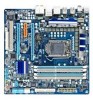
GA-P55M-UD4 LGA1156 socket motherboard for Intel® Core™ i7 processor family/ Intel® Core™ i5 processor family User's Manual Rev. 1001 12ME-P55MUD4-1001R - Gigabyte GA-P55M-UD4 | Manual - Page 2
Motherboard GA-P55M-UD4 Jul. 21, 2009 Motherboard GA-P55M-UD4 Jul. 21, 2009 - Gigabyte GA-P55M-UD4 | Manual - Page 3
at: http://www.gigabyte.com.tw Identifying Your Motherboard Revision The revision number on your motherboard looks like this: "REV: X.X." For example, "REV: 1.0" means the revision of the motherboard is 1.0. Check your motherboard revision before updating motherboard BIOS, drivers, or when looking - Gigabyte GA-P55M-UD4 | Manual - Page 4
Items...6 GA-P55M-UD4 Motherboard Layout 7 Block Diagram...8 Chapter 1 Hardware Installation 9 1-1 Installation Precautions 9 1-2 Product Specifications 10 1-3 Installing the CPU and CPU Cooler 13 1-3-1 Installing the CPU 13 1-3-2 Installing the CPU Cooler 15 1-4 Installing the Memory 16 - Gigabyte GA-P55M-UD4 | Manual - Page 5
Configuring SATA Hard Drive(s 79 5-1-1 Configuring Intel P55 SATA Controllers 79 5-1-2 Configuring GIGABYTE SATA2 SATA Controller 87 5-1-3 Making a SATA RAID/AHCI Driver Diskette 93 5-1-4 Installing the SATA RAID/AHCI Driver and Operating System 94 5-2 Configuring Audio Input and Output 105 - Gigabyte GA-P55M-UD4 | Manual - Page 6
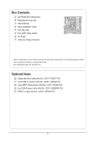
Box Contents GA-P55M-UD4 motherboard Motherboard driver disk User's Manual Quick Installation Guide One IDE cable Four SATA 3Gb/s cables I/O Shield 2-Way SLI bridge connector • The box contents above are for reference only and the actual items shall depend on the product package you obtain. The box - Gigabyte GA-P55M-UD4 | Manual - Page 7
LGA1156 PHASE LED ATX PWR_FAN R_USB_1 USB_1394_ESATA USB_LAN RTL8111D AUDIO F_AUDIO SYS_FAN1 CODEC PCIEX4 CD_IN PCIEX8 PCI IT8720 SPDIF_O SPDIF_I B_BIOS M_BIOS BAT PCIEX16 GA-P55M-UD4 DDR3_2 DDR3_1 DDR3_4 DDR3_3 IDE GIGABYTE SATA2 PW_SW TSB43AB23 Intel® P55 CMOS_SW SATA2_4 RST_SW - Gigabyte GA-P55M-UD4 | Manual - Page 8
CLK+/- (133 MHz) DDR3 2200/1333/1066/800 MHz Dual Channel Memory x16 x8 Switch PCI Express Bus PCI Express Bus x4 x1 x1 RTL8111D RJ45 GIGABYTE SATA2 1 PCI Express x4 LAN 2 SATA 3Gb/s ATA-133/100/66/33 IDE Channel PCI Bus TSB43AB23 DMI Interface Intel® P55 Dual BIOS 6 SATA 3Gb/s 14 - Gigabyte GA-P55M-UD4 | Manual - Page 9
or memory. If you do not have an ESD wrist strap, keep your hands dry and first touch a metal object to eliminate static electricity. • Prior to installing the motherboard, please have it on top of an antistatic pad or within an electrostatic shielding container. • Before unplugging the power supply - Gigabyte GA-P55M-UD4 | Manual - Page 10
™ i7 series processor/Intel® Core™ i5 series processor in the LGA1156 package (Go to GIGABYTE's website for the latest CPU support list.) L3 cache varies with CPU Chipset w Intel® P55 Express Chipset Memory Audio 4 x 1.5V DDR3 DIMM sockets supporting up to 16 GB of system memory (Note - Gigabyte GA-P55M-UD4 | Manual - Page 11
connected to the internal IEEE 1394a header) 1 x 24-pin ATX main power connector 1 x 8-pin ATX 12V power connector 1 x floppy disk drive connector 1 x IDE connector 7 x SATA 3Gb/s connectors 1 x CPU fan header 2 x system fan headers 1 x power fan header 1 x front panel header 1 x front panel audio - Gigabyte GA-P55M-UD4 | Manual - Page 12
(OEM version) Operating System w Support for Microsoft® Windows® 7/Vista/XP Form Factor w Micro ATX Form Factor; 24.4cm x 24.4cm (Note 1) Due to Windows Vista/XP 32-bit operating system limitation, when more than 4 GB of physical memory is installed, the actual memory size displayed will be - Gigabyte GA-P55M-UD4 | Manual - Page 13
motherboard supports the CPU. (Go to GIGABYTE's website for the latest CPU support list.) • Always turn off the computer and unplug the power cord from the power that the system bus frequency memory, hard drive, etc. 1-3-1 Installing the CPU A. Locate the alignment keys on the motherboard - Gigabyte GA-P55M-UD4 | Manual - Page 14
B. Follow the steps below to correctly install the CPU into the motherboard CPU socket. Before installing the CPU, make sure to turn off the computer and unplug the power cord from the power outlet to prevent damage to the CPU. Step 1: Gently press the CPU socket lever handle down and away from the - Gigabyte GA-P55M-UD4 | Manual - Page 15
CPU cooler on the motherboard. (The following procedure uses Intel® boxed cooler as the manual for instructions on installing the cooler.) Step 5: After the installation, check the back of the motherboard the power connector of the CPU cooler to the CPU fan header (CPU_FAN) on the motherboard. Use - Gigabyte GA-P55M-UD4 | Manual - Page 16
Make sure that the motherboard supports the memory. It is recommended that memory of the same capacity, brand, speed, and chips be used. (Go to GIGABYTE's website for the latest memory support list.) • Always turn off the computer and unplug the power cord from the power outlet before installing the - Gigabyte GA-P55M-UD4 | Manual - Page 17
to turn off the computer and unplug the power cord from the power outlet to prevent damage to the memory module. DDR3 and DDR2 DIMMs are not compatible to each other or DDR DIMMs. Be sure to install DDR3 DIMMs on this motherboard. Notch DDR3 DIMM A DDR3 memory module has a notch, so it can only fit - Gigabyte GA-P55M-UD4 | Manual - Page 18
you begin to install an expansion card: • Make sure the motherboard supports the expansion card. Carefully read the manual that came with your expansion card. • Always turn off the computer and unplug the power cord from the power outlet before installing an expansion card to prevent hardware damage - Gigabyte GA-P55M-UD4 | Manual - Page 19
XP operating system - A CrossFireX/SLI-supported motherboard with two PCI Express x16 slots and correct driver - Two CrossFireX/SLI-ready graphics cards of identical brand and chip and correct driver - Two CrossFire (Note)/SLI bridge connectors - A power supply with sufficient power is - Gigabyte GA-P55M-UD4 | Manual - Page 20
an external audio system that supports digital optical audio. Before using this feature, ensure that your audio system provides an optical connector, first remove the cable from your device and then remove it from the motherboard. • When removing the cable, pull it straight out from the connector. Do - Gigabyte GA-P55M-UD4 | Manual - Page 21
to perform different functions via the audio software. Only microphones still MUST be connected to the default Mic in jack ( ). Refer to the instructions on setting up a 2/4/5.1/7.1-channel audio configuration in Chapter 5, "Configuring 2/4/5.1/7.1-Channel Audio." - 21 - Hardware Installation - Gigabyte GA-P55M-UD4 | Manual - Page 22
4 19 9 10 8 13 4 15 14 6 17 20 16 21 11 1) ATX_12V_2X4 2) ATX 3) CPU_FAN 4) SYS_FAN1/2 5) PWR_FAN 6) FDD 7) IDE 8) SATA2_0/1/2/3/4 9) GSATA2_0/1 10) BAT to turn off the devices and your computer. Unplug the power cord from the power outlet to prevent damage to the devices. • After installing - Gigabyte GA-P55M-UD4 | Manual - Page 23
Intel Extreme Edition CPU (130W). • To meet expansion requirements, it is recommended that a power supply that can withstand high power consumption be used (500W or greater). If a power supply is used that does not provide the required power, the result can lead to an unstable or unbootable system - Gigabyte GA-P55M-UD4 | Manual - Page 24
a 3-pin (SYS_FAN1) system fan headers, and a 3-pin power fan header (PWR_FAN). Most fan headers possess a foolproof insertion design. When connecting a fan cable, be sure to connect it in the correct orientation (the black connector wire is the ground wire). The motherboard supports CPU fan speed - Gigabyte GA-P55M-UD4 | Manual - Page 25
are compatible with SATA 1.5Gb/s standard. Each SATA connector supports a single SATA device. The P55 Chipset supports RAID 0, RAID 1, RAID 5 and RAID 10. Refer to Chapter 5, "Configuring SATA Hard Drive(s)," for instructions on configuring a RAID array. Pin No. Definition SATA2_3 7 7 SATA2_4 - Gigabyte GA-P55M-UD4 | Manual - Page 26
supports a single SATA device. The GIGABYTE SATA2 controller supports RAID 0 and RAID 1. Refer to Chapter 5, "Configuring SATA Hard Drive(s)," for instructions drive. 10) BAT (Battery) The battery provides power to keep the values (such as BIOS configurations, date, and time information) in the - Gigabyte GA-P55M-UD4 | Manual - Page 27
problem is detected at system startup. If a problem is detected, the BIOS may issue beeps in different patterns to indicate the problem. Refer to Chapter 5, "Troubleshooting chassis. A front panel module mainly consists of power switch, reset switch, power LED, hard drive activity LED, speaker and - Gigabyte GA-P55M-UD4 | Manual - Page 28
The front panel audio header supports Intel High Definition audio (HD) and AC'97 audio. You may connect your chassis front panel audio module to this header. Make sure the wire assignments of the module connector match the pin assignments of the motherboard header. Incorrect connection between the - Gigabyte GA-P55M-UD4 | Manual - Page 29
Power 1 2 SPDIFI 3 GND 15) SPDIF_O (S/PDIF Out Header) This header supports digital S/PDIF Out and connects a S/PDIF digital audio cable (provided by expansion cards) for digital audio output from your motherboard carefully read the manual for your expansion card. Pin No. Definition 1 1 - Gigabyte GA-P55M-UD4 | Manual - Page 30
bracket (2x5-pin) cable into the USB header. • Prior to installing the USB bracket, be sure to turn off your computer and unplug the power cord from the power outlet to prevent damage to the USB bracket. 17) F1_1394 (IEEE 1394a Header, Gray) The header conforms to IEEE 1394a specification. The IEEE - Gigabyte GA-P55M-UD4 | Manual - Page 31
and unplug the power cord from the power outlet before clearing the CMOS values. • After system restart, go to BIOS Setup to load factory defaults (select Load Optimized Defaults) or manually configure the BIOS settings (refer to Chapter 2, "BIOS Setup," for BIOS configurations). - 31 - Hardware - Gigabyte GA-P55M-UD4 | Manual - Page 32
Hardware Installation - 32 - - Gigabyte GA-P55M-UD4 | Manual - Page 33
the GIGABYTE Q-Flash or @BIOS utility. • Q-Flash allows the user to quickly and easily upgrade or back up BIOS without entering the operating system. • @BIOS is a Windows-based utility that searches and downloads the latest version of BIOS from the Internet and updates the BIOS. For instructions on - Gigabyte GA-P55M-UD4 | Manual - Page 34
v6.00PG, An Energy Star Ally Copyright (C) 1984-2009, Award Software, Inc. Motherboard Model BIOS Version P55M-UD4 D3 . . . . : BIOS Setup : XpressRecovery2 : Boot Menu : Qflash 07/10/2009-P55-7A89RG0MC-00 Function Keys Function Keys SATA Mode Message: "SATA is found running - Gigabyte GA-P55M-UD4 | Manual - Page 35
Standard CMOS Features Advanced BIOS Features Integrated Peripherals Power Management Setup PC Health Status Load options. • When the system is not stable as usual, select the Load Optimized Defaults item to set your system to its defaults. • The BIOS Setup menus described in this - Gigabyte GA-P55M-UD4 | Manual - Page 36
the clock, frequency and voltages of your CPU, memory, etc. Standard CMOS Features Use this menu to configure the system time and date, hard drive types, floppy disk drive types, and the type of errors that stop the system boot, etc. Advanced BIOS Features Use this menu to configure the device - Gigabyte GA-P55M-UD4 | Manual - Page 37
Optimized Defaults (Note 1) This item is present only if you install a CPU that supports this feature. For more information about Intel CPUs' unique features, please visit Intel's website. (Note 2) This item appears only if you install a memory module that supports this feature. - 37 - BIOS Setup - Gigabyte GA-P55M-UD4 | Manual - Page 38
this function. This feature only works for operating systems that support multi-processor mode. (Default: Enabled) CPU Enhanced Halt (C1E) (Note) Enables or disables Intel CPU Enhanced Halt (C1E) function, a CPU power-saving function in system halt state. When enabled, the CPU core frequency - Gigabyte GA-P55M-UD4 | Manual - Page 39
voltage will be reduced during system halt state to decrease power consumption. The C3/C6/C7 state is a more enhanced power-saving state than C1. Auto lets the BIOS automatically configure this setting. (Default: Auto) CPU Thermal Monitor (Note) Enables or disables Intel CPU Thermal Monitor function - Gigabyte GA-P55M-UD4 | Manual - Page 40
first verify the overclocking capability of your CPU. As stability is highly dependent on system components, when system instability occurs after overclocking, lower the overclocking ratio. (Note) This item appears only if you install a memory module that supports this feature. BIOS Setup - 40 - Gigabyte GA-P55M-UD4 | Manual - Page 41
operating frequency of the memory being used; the second is the memory frequency that is automatically adjusted according to the BCLK Frequency(Mhz) and System Memory Multiplier settings. (Note) This item appears only if you install a memory module that supports this feature. - 41 - BIOS Setup - Gigabyte GA-P55M-UD4 | Manual - Page 42
system operate at its best performance level. DRAM Timing Selectable (SPD) Quick and Expert allows the Channel Interleaving and Rank Interleaving items to be configurable. Options are: Auto (default), Quick, Expert. Profile DDR Voltage When using a non-XMP memory Defaults BIOS Setup - 42 - - Gigabyte GA-P55M-UD4 | Manual - Page 43
Options are: Auto (default), 1~63. Command Rate(CMD) Options are: Auto (default), 1~3. >>>>> Channel A/B Misc Timing Control Round Trip Latency Options are: Auto (default), 1~255. - 43 - BIOS Setup - Gigabyte GA-P55M-UD4 | Manual - Page 44
are: Auto (default), 1~8. Different Ranks Options are: Auto (default), 1~8. On The Same Rank Options are: Auto (default), 1~2. ESC: Exit F1: General Help F7: Optimized Defaults BIOS Setup - 44 - - Gigabyte GA-P55M-UD4 | Manual - Page 45
keeping the CPU voltage more constant under light and heavy CPU load. Disabled sets the CPU voltage following Intel specifications. (Default: Disabled) Note: Enabling Load-Line Calibration may result in damage to your CPU . The default is Auto. Ch-B Data VRef. The default is Auto. - 45 - BIOS Setup - Gigabyte GA-P55M-UD4 | Manual - Page 46
ESC: Exit F1: General Help F7: Optimized Defaults Isochronous Support Determines whether to enable specific streams within the CPU and Chipset Enter] Item Help Menu Level BIOS Version BCLK CPU Frequency Memory Frequency Total Memory Size D3 133.27 MHz 2265.57 - Gigabyte GA-P55M-UD4 | Manual - Page 47
Memory 1022M 1024M Item Help Menu Level Move Enter: Select F5: Previous Values +/-/PU/PD: Value F10: Save F6: Fail-Safe Defaults ESC: Exit F1: General Help F7: Optimized Defaults Date (mm:dd:yy) Sets the system devices by using one of the three methods below: - 47 - BIOS Setup - Gigabyte GA-P55M-UD4 | Manual - Page 48
only and are determined by the BIOS POST. Base Memory Also called conventional memory. Typically, 640 KB will be reserved for the MS-DOS operating system. Extended Memory The amount of extended memory. Total Memory The total amount of memory installed on the system. BIOS Setup - 48 - - Gigabyte GA-P55M-UD4 | Manual - Page 49
allows your system to report read/write errors of the hard drive and to issue warnings when a third party hardware monitor utility is installed. (Default: Disabled) (Note) This item is present only if you install a CPU that supports this feature. For more information about Intel CPUs' unique - Gigabyte GA-P55M-UD4 | Manual - Page 50
Disabled) No-Execute Memory Protect (Note) Enables or disables Intel Execute Disable Bit function. This function may enhance protection for the computer, reducing exposure to viruses and malicious buffer overflow attacks when working with its supporting software and system. (Default: Enabled) Delay - Gigabyte GA-P55M-UD4 | Manual - Page 51
driver to enable advanced Serial ATA features such as Native Command Queuing and hot plug. SATA Port0-3 Native Mode (Intel P55 Native IDE mode if you wish to install operating systems that support Native mode. USB Controllers Enables or disables the integrated Enabled) - 51 - BIOS Setup - Gigabyte GA-P55M-UD4 | Manual - Page 52
function and Green LAN are enabled, the system will dynamically detect if a LAN cable is If no LAN cable is attached to the motherboard, the Status fields of all four pairs of When LAN Cable Is Functioning Normally... If no cable problem is detected on the LAN cable connected to a BIOS Setup - 52 - - Gigabyte GA-P55M-UD4 | Manual - Page 53
Problem Occurs... If a cable problem /IDE Device (GIGABYTE SATA2, IDE and GSATA2_0/1 Connectors) Enables or disables the SATA controller integrated in the GIGABYTE SATA2 chip or configures the SATA an interface specification that allows the storage driver to enable advanced Serial ATA features - Gigabyte GA-P55M-UD4 | Manual - Page 54
ATX power supply providing at least 1A on the +5VSB lead. (Default: Enabled) Power On by Ring Allows the system to be awakened from an ACPI sleep state by a wake-up signal from a modem that supports wake-up function. (Default: Enabled) (Note) Supported on Windows Vista operating system only. BIOS - Gigabyte GA-P55M-UD4 | Manual - Page 55
Windows Vista. This item is configurable only if the HPET Support is set to Enabled. (Default: 32-bit mode) Power On By Mouse Allows the system to be turned on by a PS/2 mouse wake-up event. Note: To use this function, you need an ATX power supply providing at least 1A on the +5VSB lead. Disabled - Gigabyte GA-P55M-UD4 | Manual - Page 56
device attached to the motherboard CI header. If the system chassis cover is removed, BIOS will emit warning sound. Options are: Disabled (default), 60oC/140oF, 70oC/158oF, 80oC/176oF, 90oC/194oF. CPU/SYSTEM/POWER FAN Fail Warning Allows the system to emit warning sound if the CPU/system/power - Gigabyte GA-P55M-UD4 | Manual - Page 57
configurable only if CPU Smart FAN Control is set to Enabled. Auto Lets the BIOS automatically detect the type of CPU fan installed and sets the optimal CPU fan fan that is not designed following Intel PWM fan specifications, selecting PWM mode may not effectively reduce the fan speed. - 57 - Gigabyte GA-P55M-UD4 | Manual - Page 58
this item and then press the key to load the safest BIOS default settings. In case system instability occurs, you may try to load Fail-Safe defaults, which are the safest and most stable BIOS settings for the motherboard. 2-10 Load Optimized Defaults CMOS Setup Utility-Copyright (C) 1984-2009 - Gigabyte GA-P55M-UD4 | Manual - Page 59
Standard CMOS Features Advanced BIOS Features Integrated Peripherals Power Management SetupEnter Password: PC BIOS Setup and making BIOS changes. When the Password Check item is set to System, you must enter the supervisor password (or user password) at system startup and when entering BIOS - Gigabyte GA-P55M-UD4 | Manual - Page 60
Tweaker(M.I.T.) Load Fail-Safe Defaults Standard CMOS Features Advanced BIOS Features Load Optimized Defaults Quit Without Saving (YSe/Nt S)?upNervisor Password Integrated Peripherals Set User Password Power Management Setup Save & Exit Setup PC Health Status Exit Without - Gigabyte GA-P55M-UD4 | Manual - Page 61
are installed, follow the on-screen instructions to restart your system. You can install other applications included in the motherboard driver disk. • For USB 2.0 driver support under the Windows XP operating system, please install the Windows XP Service Pack 1 or later. After installing the SP1 - Gigabyte GA-P55M-UD4 | Manual - Page 62
applications that GIGABYTE develops and some free software. You can click the Install button on the right of an item to install it. 3-3 Technical Manuals This page provides GIGABYTE's application guides, content descriptions for this driver disk, and the motherboard manuals. Drivers Installation - Gigabyte GA-P55M-UD4 | Manual - Page 63
3-4 Contact For the detailed contact information of the GIGABYTE Taiwan headquarter or worldwide branch offices, click the URL on this page to link to the GIGABYTE website. 3-5 System This page provides the basic system information. - 63 - Drivers Installation - Gigabyte GA-P55M-UD4 | Manual - Page 64
3-6 Download Center To update the BIOS, drivers, or applications, click the Download Center button to link to the GIGABYTE website. The latest version of the BIOS, drivers, or applications will be displayed. 3-7 New Utilities This page provides a quick link to GIGABYTE's lately developed utilities - Gigabyte GA-P55M-UD4 | Manual - Page 65
the operating system and drivers are installed. • The amount of data and hard drive access speed may affect the speed at which the data is backed up/ restored. • It takes longer to back up a hard drive than to restore it. System Requirements: • At least 512 MB of system memory • VESA compatible - Gigabyte GA-P55M-UD4 | Manual - Page 66
of data) and begin the installation of the operating system. Step 4: After the operating system is installed, right-click the Computer icon on your save the backup file. B. Accessing Xpress Recovery2 1. Boot from the motherboard driver disk to access Xpress Recovery2 for the first time. When you - Gigabyte GA-P55M-UD4 | Manual - Page 67
D. Using the Restore Function in Xpress Recovery2 Select RESTORE to restore the backup to your hard drive in case the system breaks down. The RESTORE option will not be present if no backup is created before. E. Removing the Backup Step 1: If you wish to remove the - Gigabyte GA-P55M-UD4 | Manual - Page 68
-2009, Award Software, Inc. P55M-UD4 D3 . . . . : BIOS Setup : XpressRecovery2 : Boot Menu : Qflash 07/10/2009-P55-7A89RG0MC-00 Because BIOS flashing is potentially risky, please do it with caution. Inadequate BIOS flashing may result in system malfunction. Unique Features - 68 - Gigabyte GA-P55M-UD4 | Manual - Page 69
Drive Enter : Run hi:Move ESC:Reset F10:Power Off Total size : 0 Free size : 0 3. Select the BIOS update file and press . Make sure the BIOS update file matches your motherboard model. Step 2: The process of the system reading the BIOS file from the floppy disk is displayed on the - Gigabyte GA-P55M-UD4 | Manual - Page 70
BIOS Setup. Select Load Optimized Defaults and press to load BIOS defaults. System will re-detect all peripheral devices after a BIOS update, so we recommend that you reload BIOS Advanced BIOS Features Set Supervisor Password Integrated Peripherals Set User Password Power Management - Gigabyte GA-P55M-UD4 | Manual - Page 71
. If the BIOS update file for your motherboard is not present on the @BIOS server site, please manually download the BIOS update file from GIGABYTE's website and follow the instructions in "Update the BIOS without Using the Internet Update Function" below. 2. Update the BIOS without Using the - Gigabyte GA-P55M-UD4 | Manual - Page 72
install a DDR3 1066 MHz memory module(s) (or above) to enable support for Quick Boost. Available functions in EasyTune 6 may differ by motherboard model. Grayed-out area(s) indicates that the item is not configurable or the function is not supported. Incorrectly doing overclock/overvoltage may - Gigabyte GA-P55M-UD4 | Manual - Page 73
software design, GIGABYTE Dynamic Energy Saver™ 2 is able to provide exceptional power savings and enhanced power efficiency without Update (Check for the latest utility version) • The above data is for reference only. Actual performance may vary depending on motherboard model. • CPU Power and Power - Gigabyte GA-P55M-UD4 | Manual - Page 74
taskbar) 13 INFO/Help 14 Motherboard Phase LED On/Off Switch (Default: On) 15 Live Utility Update (Check for the latest utility version) C. Stealth Mode In Stealth Mode, the system continues to work with the user-defined power saving settings, even after the system is restarted. Re-enter the - Gigabyte GA-P55M-UD4 | Manual - Page 75
for using Q-Share After installing Q-Share from the motherboard driver disk, go to Start>All Programs>GIGABYTE>Q-Share. exe to launch the Q-Share tool. shared data folder Changes the data folder to be shared (Note) Updates Q-Share online Displays the current Q-Share version Exits Q-Share ( - Gigabyte GA-P55M-UD4 | Manual - Page 76
entering the operating system, delivering greater efficiency for daily use. Instructions: Select the Enable check box below the BIOS QuickBoot or OS QuickBoot item and then click Save to save the settings. SMART QuickBoost SMART QuickBoost features quick and effortless CPU overclocking for novice - Gigabyte GA-P55M-UD4 | Manual - Page 77
, and remind users of the dates. It also stores the recorded data in the main and backup BIOS simultaneously, which can prevent loss of the data in case the system/hard drive fails. Instructions: Enter the Smart 6™ password to launch the SMART DualBIOS utility. You can record personal passwords and - Gigabyte GA-P55M-UD4 | Manual - Page 78
storage device (Note 5). Instructions: Select the Enable check box at the bottom of the ON/OFF Recorder or File Monitor tab to enable the recording of system on/off time or Password in the system BIOS Setup program to prevent the system time being changed by other users. Unique Features - 78 - - Gigabyte GA-P55M-UD4 | Manual - Page 79
," to identify the SATA controller for the SATA port. (For example, on this motherboard, the SATA2_0, SATA2_1, SATA2_2, SATA2_3, and SATA2_4 ports are supported by P55 Chipset.) Then connect the power connector from your power supply to the hard drive. (Note 1) Skip this step if you do not want - Gigabyte GA-P55M-UD4 | Manual - Page 80
mode correctly in system BIOS Setup. Step 1: Turn on your computer and press to enter BIOS Setup during the POST (Power-On Self-Test). and exit BIOS Setup. The BIOS Setup menus described in this section may differ from the exact settings for your motherboard. The actual BIOS Setup menu - Gigabyte GA-P55M-UD4 | Manual - Page 81
configuration. Step 1: After the POST memory test begins and before the operating system boot begins, look for a message which says "Press to enter Configuration Utility" (Figure 2). Press + to enter the P55 RAID Configuration Utility. Intel(R) Matrix Storage Manager option ROM - Gigabyte GA-P55M-UD4 | Manual - Page 82
. Then, select a RAID level (Figure 4). RAID levels supported include RAID 0, RAID 1, Recovery, RAID 10, and RAID 5 (the selections available depend on the number of the hard drives being installed). Press to proceed. Intel(R) Matrix Storage Manager option ROM v8.9.0.1023 PCH-D wRAID5 - Gigabyte GA-P55M-UD4 | Manual - Page 83
Figure 6). Intel(R) Matrix Storage Manager option ROM v8.9.0.1023 PCH-D wRAID5 Copyright(C) 2003-09 Intel Corporation. BIOS utility, press or select 5. Exit in MAIN MENU. Now, you can proceed to create the SATA RAID/AHCI driver diskette and install the SATA RAID/AHCI driver and operating system - Gigabyte GA-P55M-UD4 | Manual - Page 84
, you are unable to create a RAID array. • Only the master drive can be riewed in the operating system; the recovery drive is hidden. Step 1: select Create RAID Volume in MAIN MENU and press (Figure 8). Intel(R) Matrix Storage Manager option ROM v8.9.0.1023 PCH-D wRAID5 Copyright(C) 2003-09 - Gigabyte GA-P55M-UD4 | Manual - Page 85
system. On Request allows users to update data from the master drive to the recovery drive manually using the Update Volume function of the Intel Matrix Storage Console in the operating system : On Request: volume is updated manually Continuous: volume is updated automatically [hi]-Change [TAB]- - Gigabyte GA-P55M-UD4 | Manual - Page 86
When prompted to confirm your selection (Figure 12), press to confirm or to abort. Intel(R) Matrix Storage Manager option ROM v8.9.0.1023 PCH-D wRAID5 Copyright(C) 2003-09 Intel Corporation. All Rights Reserved. Name Volume0 Level RAID0(Stripe) [ DELETE VOLUME MENU ] Drives 2 Capacity - Gigabyte GA-P55M-UD4 | Manual - Page 87
motherboard, the GSATA2_0 and GSATA2_1 ports are supported by the GIGABYTE SATA2 SATA controller. Then connect the power connector from your power supply to the hard drive. B. Configuring SATA controller mode in BIOS Setup Make sure to configure the SATA controller mode correctly in system BIOS - Gigabyte GA-P55M-UD4 | Manual - Page 88
a non-RAID configuration. After the POST memory test begins and before the operating system boot begins, look for a message which says "Press to enter RAID Setup Utility" (Figure 2). Press + to enter the RAID setup utility. GIGABYTE Technology Corp. PCI Express to SATAII HOST - Gigabyte GA-P55M-UD4 | Manual - Page 89
Create RAID Disk Drive item. Then the Create New RAID screen appears (Figure 4). Gigabyte Technology Corp. RAID Setup Utility v1.07.06 [ Create New RAID ] Name in length for the created RAID drive to be identified by system BIOS or OS. [fg]-Move Cursor [DEL,BS]-Delete Character Figure 4 [ - Gigabyte GA-P55M-UD4 | Manual - Page 90
Disks: After a RAID mode is selected, RAID BIOS automatically assigns the two hard drives installed as the New RAID ] Name: Level: Disks: Block: Size: GRAID 0-Stripe Select Disk 128 KB 240 GB Gigabyte Technology Corp. RAID Setup Utility v1.07.06 [ Hard Disk Drive List ] Model Name } HDD0: - Gigabyte GA-P55M-UD4 | Manual - Page 91
Drive List block. Select the array and press . A small window displaying the array information will appear in the center of the screen (Figure 9). Gigabyte Technology Corp. RAID Setup Utility v1.07.06 [ Main Menu ] Create RAID Disk Drive Delete RAID Disk Drive Revert HDD to Non-RAID Solve - Gigabyte GA-P55M-UD4 | Manual - Page 92
screen to save your settings before exiting the RAID BIOS utility, then press (Figure 10). [ Save And Exit Setup Exit Without Saving Gigabyte Technology Corp. RAID Setup Utility v1.07 RAID/AHCI driver diskette and the installation of the SATA RAID/ AHCI driver and operating system. Delete the - Gigabyte GA-P55M-UD4 | Manual - Page 93
: • For the Intel P55, type (Figure 1): (Note) A:\>copy d:\bootdrv\imsm\32bit\*.* • For the GIGABYTE SATA2, type (Figure 2): (Note) A:\>copy d:\bootdrv\gsata\32bit\*.* Figure 1 In Windows mode: Figure 2 Steps: 1: Use an alternative system and insert the motherboard driver disk. 2: From - Gigabyte GA-P55M-UD4 | Manual - Page 94
Installing the SATA RAID/AHCI Driver and Operating System With the SATA RAID/AHCI driver diskette and correct BIOS settings, you are ready third party SCSI or RAID driver. Figure 1 Step 2: For the Intel P55: Insert the floppy disk containing the SATA RAID/AHCI driver and press . Then a controller - Gigabyte GA-P55M-UD4 | Manual - Page 95
Figure 3 below will appear. Select (Windows XP/2003) RAID/AHCI Driver for GIGABYTE GBB36X Controller and press . Windows Setup You have chosen to configure a SCSI Adapter for use with Windows, using a device support disk provided by an adapter manufacturer. Select the SCSI Adapter you - Gigabyte GA-P55M-UD4 | Manual - Page 96
exists in your system.) For the Intel P55: Step 1: Restart your system to boot from the Windows Vista setup disk and perform standard OS installation steps. When a screen similar to that below appears, select Load Driver (Figure 4). Figure 4 Step 2: Insert the motherboard driver disk (Method A) or - Gigabyte GA-P55M-UD4 | Manual - Page 97
shown in Figure 6 appears, select Intel(R) ICH8R/ICH9R/ICH10R/DO/PCH SATA RAID Controller and click Next. Figure 6 Step 4: After the driver is loaded, select the RAID/AHCI drive(s) where you want to install the operating system and then click Next to continue the OS installation (Figure 7). Figure - Gigabyte GA-P55M-UD4 | Manual - Page 98
your system to boot from the Windows Vista setup disk and perform standard OS installation steps. When a screen similar to that below appears (RAID/AHCI hard drive(s) will not be detected at this stage), select Load Driver (Figure 8). Figure 8 Step 2: Insert the motherboard driver disk (Method - Gigabyte GA-P55M-UD4 | Manual - Page 99
as shown in Figure 10 appears, select GIGABYTE GBB36X Controller and click Next. Figure 10 Step 4: After the driver is loaded, select the RAID/AHCI drive(s) where you want to install the operating system and then click Next to continue the OS installation (Figure 11). Figure 11 - 99 - Appendix - Gigabyte GA-P55M-UD4 | Manual - Page 100
drive must have equal or greater capacity than the old one.) For the Intel P55: Turn off your computer and replace the failed hard drive with a new stage, you have to manually rebuild the array in the operating system (see the next page for more details). Intel(R) Matrix Storage Manager option - Gigabyte GA-P55M-UD4 | Manual - Page 101
System While in the operating system, make sure the chipset driver has been installed from the motherboard driver disk. Then launch the Intel Matrix Storage Console from All Programs in the Start menu. Step 1: On the View menu of the Intel . Follow the on-screen instructions to proceed. Step 4: To - Gigabyte GA-P55M-UD4 | Manual - Page 102
are set to Recovery Volume in Update on Request mode, you can P55 RAID Configuration Utility. On the RECOVERY OPTIONS menu, select Enable Only Recovery Disk to show the recovery drive in the operating system. Follow the on-screen instructions to complete and exit the RAID Configuration Utility. Intel - Gigabyte GA-P55M-UD4 | Manual - Page 103
: Turn off your computer and replace the failed hard drive with a new one. Use either the RAID setup utility or the GIGABYTE RAID CONFIGURER utility in the operating system to perform the rebuild. • Rebuilding with the RAID setup utility Step 1: When the message "Press to enter RAID Setup - Gigabyte GA-P55M-UD4 | Manual - Page 104
• Rebuilding in the operating system Make sure the GIGABYTE SATA2 SATA controller driver has been installed from the motherboard driver disk. Launch the GIGABYTE RAID CONFIGURER from All Programs in the Start menu. Step 1: In the GIGABYTE RAID CONFIGURER screen, right-click on the array to be - Gigabyte GA-P55M-UD4 | Manual - Page 105
2/4/5.1/7.1-Channel Audio The motherboard provides six audio jacks on the back panel which support 2/4/5.1/7.1-channel (Note) Configuring Speakers (The following instructions use Windows Vista as the example operating system.) Step 1: After installing the audio driver, the HD Audio Manager icon - Gigabyte GA-P55M-UD4 | Manual - Page 106
Step 2: Connect an audio device to an audio jack. The The current connected device is dialog box appears. Select the device according to the type of device you connect. Then click OK. Step 3: On the Speakers screen, click the Speaker Configuration tab. In the Speaker Configuration list, select - Gigabyte GA-P55M-UD4 | Manual - Page 107
S/PDIF In 1. Installing the S/PDIF In Cable: Step 1: First, attach the connector at the end of the cable to the SPDIF_I header on your motherboard. Step 2: Secure the metal bracket to the chassis back panel with a screw. 2. Configuring S/PDIF In: On the Digital Input screen, click the Default - Gigabyte GA-P55M-UD4 | Manual - Page 108
B. S/PDIF Out The S/PDIF Out jacks can transmit audio signals to an external decoder for decoding to get the best audio quality. 1. Connecting a S/PDIF Out Cable: S/PDIF Coaxial Cable S/PDIF Optical Cable Connect a S/PDIF coaxial cable or a S/PDIF optical cable (either one) to an external decoder - Gigabyte GA-P55M-UD4 | Manual - Page 109
the motherboard driver disk. Click the Start icon Programs, Dolby Control Center to access the utility. (The following illustration demonstrates a 7.1-speaker configuration as an example.) . Point to All 1. : Click Dolby Pro Logic IIx. The system will expand 2-channel audio for a 7.1-channel - Gigabyte GA-P55M-UD4 | Manual - Page 110
5-2-4 Configuring Microphone Recording Step 1: After installing the audio driver, the HD Audio Manager icon will appear in the notification area. Double-click the icon to access the HD Audio Manager. Step 2: Connect your microphone - Gigabyte GA-P55M-UD4 | Manual - Page 111
Step 4: To raise the recording and playback volume for the microphone, click the Microphone Boost icon on the right of the Recording Volume slider and set the Microphone Boost level. Step 5: After completing the settings above, click Start, point to All Programs, point to Accessories, and then click - Gigabyte GA-P55M-UD4 | Manual - Page 112
. Be sure to save the recorded audio file upon completion. B. Playing the Recorded Sound You can play your recording in a digital media player program that supports your audio file format. Appendix - 112 - - Gigabyte GA-P55M-UD4 | Manual - Page 113
the Support&Downloads\Motherboards\FAQ page on our website and search for "onboard HD audio driver." Q: What do the beeps emitted during the POST mean? A: The following Award BIOS beep code descriptions may help you identify possible computer problems. (For reference only.) 1 short: System boots - Gigabyte GA-P55M-UD4 | Manual - Page 114
Procedure If you encounter any troubles during system startup, follow the troubleshooting procedure below to solve the problem. START Turn off the power. Remove all peripherals, connecting cables, and power cord etc. Make sure the motherboard does not short-circuit with the chassis or - Gigabyte GA-P55M-UD4 | Manual - Page 115
is turned on, is the CPU cooler running? No The power supply, CPU or CPU socket might fail. Yes Check if there is display on your monitor. Yes Turn off the computer. Plug in the keyboard and mouse and restart the computer. The problem is verified and solved. No The graphics card, expansion - Gigabyte GA-P55M-UD4 | Manual - Page 116
GIGABYTE. Our Commitment to Preserving the Environment In addition to high-efficiency performance, all GIGABYTE motherboards local government office, your household waste disposal service or where you purchased the product for user's manual and we will be glad to help you with your effort. Appendix - Gigabyte GA-P55M-UD4 | Manual - Page 117
that potentially hazardous substances are not released into the environment and are disposed of properly. China Restriction of Hazardous Substances Table The following table is supplied in compliance with China's Restriction of Hazardous Substances (China RoHS) requirements: - 117 - Appendix - Gigabyte GA-P55M-UD4 | Manual - Page 118
Appendix - 118 - - Gigabyte GA-P55M-UD4 | Manual - Page 119
231, Taiwan TEL: +886-2-8912-4000 FAX: +886-2-8912-4003 Tech. and Non-Tech. Support (Sales/Marketing) : http://ggts.gigabyte.com.tw WEB address (English): http://www.gigabyte.com.tw WEB address (Chinese): http://www.gigabyte.tw • G.B.T. INC. - U.S.A. TEL: +1-626-854-9338 FAX: +1-626-854-9339 Tech - Gigabyte GA-P55M-UD4 | Manual - Page 120
yu • Kazakhstan WEB address : http://www.giga-byte.kz You may go to the GIGABYTE website, select your language in the language list on the top right corner of the website. • GIGABYTE Global Service System To submit a technical or non-technical (Sales/Marketing) question, please link to: http://ggts
-
 1
1 -
 2
2 -
 3
3 -
 4
4 -
 5
5 -
 6
6 -
 7
7 -
8
-
9
-
10
-
11
-
12
-
13
-
14
-
15
-
16
-
17
-
18
-
19
-
20
-
21
-
22
-
23
-
24
-
25
-
26
-
27
-
28
-
29
-
30
-
31
-
32
-
33
-
34
-
35
-
36
-
37
-
38
-
39
-
40
-
41
-
42
-
43
-
44
-
45
-
46
-
47
-
48
-
49
-
50
-
51
-
52
-
53
-
54
-
55
-
56
-
57
-
58
-
59
-
60
-
61
-
62
-
63
-
64
-
65
-
66
-
67
-
68
-
69
-
70
-
71
-
72
-
73
-
74
-
75
-
76
-
77
-
78
-
79
-
80
-
81
-
82
-
83
-
84
-
85
-
86
-
87
-
88
-
89
-
90
-
91
-
92
-
93
-
94
-
95
-
96
-
97
-
98
-
99
-
100
-
101
-
102
-
103
-
104
-
105
-
106
-
107
-
108
-
109
-
110
-
111
-
112
-
113
-
114
-
115
-
116
-
117
-
118
-
119
-
120
 |
 |

GA-P55M-UD4
LGA1156 socket motherboard for Intel
®
Core
™
i7 processor family/
Intel
®
Core
™
i5 processor family
User's Manual
Rev. 1001
12ME-P55MUD4-1001R