Gigabyte GA-P55M-UD4 Manual - Page 31
PHASE LED, 20/21 PW_SW/ CMOS_SW/ RST_SW Quick Buttons, Load Optimized De, faults
 |
UPC - 818313008572
View all Gigabyte GA-P55M-UD4 manuals
Add to My Manuals
Save this manual to your list of manuals |
Page 31 highlights
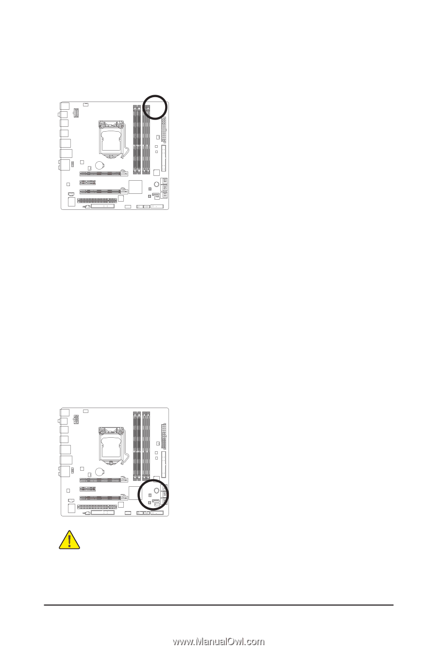
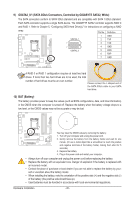
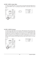
18) PHASE LED The number of lighted LEDs indicates the CPU loading. The higher the CPU loading, the more the number of lighted LEDs. To enable the Phase LED display function, please first enable Dynamic Energy Saver™ 2. Refer to Chapter 4, "Dynamic Energy Saver™ 2," for more details. 19/20/21) PW_SW/ CMOS_SW/ RST_SW (Quick Buttons) This motherboard has 3 quick buttons: power button, clearing CMOS button and reset button. The power button and reset button allow users to quickly turn on/off or reset the computer in an open-case environment when they want to change hardware components or conduct hardware testing. Use the clearing CMOS button to clear the CMOS values (e.g. date information and BIOS configurations) and reset the CMOS values to factory defaults when needed. • Always turn off your computer and unplug the power cord from the power outlet before clearing the CMOS values. • After system restart, go to BIOS Setup to load factory defaults (select Load Optimized Defaults) or manually configure the BIOS settings (refer to Chapter 2, "BIOS Setup," for BIOS configurations). - 31 - Hardware Installation
-
 1
1 -
2
-
3
-
4
-
5
-
6
-
7
-
8
-
9
-
10
-
11
-
12
-
13
-
14
-
15
-
16
-
17
-
18
-
19
-
20
-
21
-
22
-
23
-
24
-
25
-
 26
26 -
 27
27 -
 28
28 -
 29
29 -
 30
30 -
 31
31 -
 32
32 -
 33
33 -
 34
34 -
 35
35 -
 36
36 -
37
-
38
-
39
-
40
-
41
-
42
-
43
-
44
-
45
-
46
-
47
-
48
-
49
-
50
-
51
-
52
-
53
-
54
-
55
-
56
-
57
-
58
-
59
-
60
-
61
-
62
-
63
-
64
-
65
-
66
-
67
-
68
-
69
-
70
-
71
-
72
-
73
-
74
-
75
-
76
-
77
-
78
-
79
-
80
-
81
-
82
-
83
-
84
-
85
-
86
-
87
-
88
-
89
-
90
-
91
-
92
-
93
-
94
-
95
-
96
-
97
-
98
-
99
-
100
-
101
-
102
-
103
-
104
-
105
-
106
-
107
-
108
-
109
-
110
-
111
-
112
-
113
-
114
-
115
-
116
-
117
-
118
-
119
-
120
 |
 |