Gigabyte GA-Q77M-D2H Manual - Page 23
CLR_CMOS Clear CMOS Jumper, DEBUG PORT Debug Card Header, After system restart
 |
View all Gigabyte GA-Q77M-D2H manuals
Add to My Manuals
Save this manual to your list of manuals |
Page 23 highlights
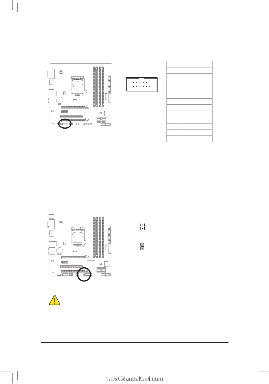
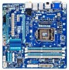
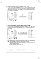
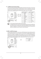
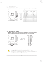
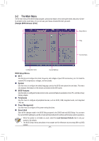
15) DEBUG PORT (Debug Card Header) (Note) This header can connect a debug card. 11 1 12 2 Pin No. 1 2 3 4 5 6 7 8 9 10 11 12 Definition No Pin GND VCC3 LAD0 LAD1 LAD2 LAD3 -LFRAME -PFMRST DB CLK DB_P_SENSOR NC 16) CLR_CMOS (Clear CMOS Jumper) Use this jumper to clear the CMOS values (e.g. date information and BIOS configurations) and reset the CMOS values to factory defaults. To clear the CMOS values, use a metal object like a screwdriver to touch the two pins for a few seconds. Open: Normal Short: Clear CMOS Values •• Always turn off your computer and unplug the power cord from the power outlet before clearing the CMOS values. •• After system restart, go to BIOS Setup to load factory defaults (select Load Optimized Defaults) or manually configure the BIOS settings (refer to Chapter 2, "BIOS Setup," for BIOS configurations). (Note) Whether this feature is supported depends on the product being received. - 23 -
-
 1
1 -
2
-
3
-
4
-
5
-
6
-
7
-
8
-
9
-
10
-
11
-
12
-
13
-
14
-
15
-
16
-
17
-
 18
18 -
 19
19 -
 20
20 -
 21
21 -
 22
22 -
 23
23 -
 24
24 -
 25
25 -
 26
26 -
 27
27 -
 28
28 -
29
-
30
-
31
-
32
-
33
-
34
-
35
-
36
-
37
-
38
-
39
-
40
-
41
-
42
-
43
-
44
-
45
-
46
-
47
-
48
-
49
-
50
-
51
-
52
 |
 |