Gigabyte GA-Q87N User Manual - Page 15
CLR_CMOS Clear CMOS Jumper, F_PANEL Front Panel Header
 |
View all Gigabyte GA-Q87N manuals
Add to My Manuals
Save this manual to your list of manuals |
Page 15 highlights
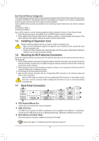
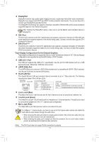
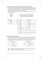
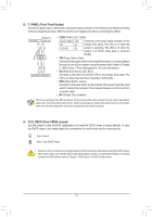
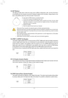
8) F_PANEL (Front Panel Header) Connect the power switch, reset switch, and system status indicator on the chassis to this header according to the pin assignments below. Note the positive and negative pins before connecting the cables. Reset Switch Hard Drive Activity LED NC RES+ RESHD- HD+ 9 1 10 2 PWPW+ PLEDPLED+ Power Switch Power LED •• PLED (Power LED, Yellow): System Status LED S0 On S3/S4/S5 Off Connects to the power status indicator on the chassis front panel. The LED is on when the system is operating. The LED is off when the system is in S3/S4 sleep state or powered off (S5). •• PW (Power Switch, Red): Connects to the power switch on the chassis front panel. You may configure the way to turn off your system using the power switch (refer to Chapter 2, "BIOS Setup," "Power Management," for more information). •• HD (Hard Drive Activity LED, Blue): Connects to the hard drive activity LED on the chassis front panel. The LED is on when the hard drive is reading or writing data. •• RES (Reset Switch, Green): Connects to the reset switch on the chassis front panel. Press the reset switch to restart the computer if the computer freezes and fails to perform a normal restart. •• NC (Purple): No connection. The front panel design may differ by chassis. A front panel module mainly consists of power switch, reset switch, power LED, hard drive activity LED and etc. When connecting your chassis front panel module to this header, make sure the wire assignments and the pin assignments are matched correctly. 9) CLR_CMOS (Clear CMOS Jumper) Use this jumper to clear the BIOS configuration and reset the CMOS values to factory defaults. To clear the CMOS values, use a metal object like a screwdriver to touch the two pins for a few seconds. Open: Normal Short: Clear CMOS Values •• Always turn off your computer and unplug the power cord from the power outlet before clearing the CMOS values. •• After system restart, go to BIOS Setup to load factory defaults (select Load Optimized Defaults) or manually configure the BIOS settings (refer to Chapter 2, "BIOS Setup," for BIOS configurations). - 15 -
-
 1
1 -
2
-
3
-
4
-
5
-
6
-
7
-
8
-
9
-
 10
10 -
 11
11 -
 12
12 -
 13
13 -
 14
14 -
 15
15 -
 16
16 -
 17
17 -
 18
18 -
 19
19 -
 20
20 -
21
-
22
-
23
-
24
-
25
-
26
-
27
-
28
-
29
-
30
-
31
-
32
-
33
-
34
-
35
-
36
 |
 |
