Gigabyte GA-Z270-Gaming K3 Users Manual - Page 14
SYS_FAN3_PUMP System Fan/Water Cooling Pump Header, CPU_OPT Water Cooling CPU Fan Header
 |
View all Gigabyte GA-Z270-Gaming K3 manuals
Add to My Manuals
Save this manual to your list of manuals |
Page 14 highlights
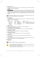
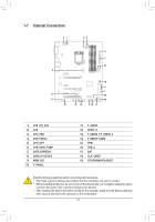
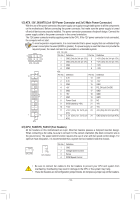
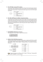
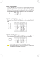
F_USB30 F_ U F_ 1 23 1 23 1 1 5) CPU_OPT (Water Cooling CPU Fan Header) B SS The fan header is 4-pin and possesses aB_foolproof insertion design. Most fan headers possess a foolproof 1 insertion design. When connecting a fan cable, be sure to connect it in the cor1rect orientation (the black 1 connector wire is the ground wire). The speed control function requires the use of a fan with fan_Sspeed control design. Pin No. Definition B_ 1 GND 1 2 Voltage Speed Control 3 Sense 1 1 B SS 1 S _S 1 23 4 PWM Speed Control 1 23 1 23 6) SYS_FAN3_PUMP (System Fan/Water Cooling Pump Header) The pump header is 4-pin and possesses a foolprooSf insertion design. Most fan S headers possess a foolproof 1 23 insertion design. When connecting a fan cable, be sure to connect it in the correct orientation (the black connector wire is the ground wire). The speed control function requires the use of a fan with fan speed control 1 23 design. For optimum heat dissipation, it is recommended that a system fan be ins1t2a3lled inside the chassis. The header also provides for more information speed control for a water cSooling pump, refer to Chapter 2, "BIOS Setup," "M.I.T.," Pin No. Definition 1 GND 1 2 Voltage Speed Control 3 Sense S3 B SS S 4 PWM Speed Control U __ 3 7) SATA EXPRESS (SATA Express Connector) Each SATA S_ Express coSnne3ctor supports a single SBATSAS ExprSess device. U __ SF _ DEBUG PORT DEBUG S_ PORT SF 8) SATA3 0/1/2/3/4/5 (SATA 6Gb/s Connectors) _ The SATA connectors conform to SATA 6Gb/s sBta_ ndard and aSre c_oSmpatible wi_th SATA 3Gb/s and SATA 1.5Gb/s standard. Each SATA connector supports a single SATA device. The Intel® Chipset supports RAID 0, RAID 1, RAID 5, and RAID 10. Refer to Chapter 3, "Configuring a RAID Set," for instructions on configuring a RAID array. SATA3 5 4 10 7S _ 1 Pin No. B_ 1 2 Definition GSND _S TXP _ 7 1 3 TXN 4 GND 1 7 SASTA3 _ 2 3 1 7 5 RXN 6 RXP 7 GND _ To enable hot-plugging for the SATA ports, refer to Chapter 2, "BIOS Setup," "Peripherals\SATA And RST Configuration," for more information. 3 _ _B _ _B - 14 - _ S_
-
 1
1 -
2
-
3
-
4
-
5
-
6
-
7
-
8
-
 9
9 -
 10
10 -
 11
11 -
 12
12 -
 13
13 -
 14
14 -
 15
15 -
 16
16 -
 17
17 -
 18
18 -
 19
19 -
20
-
21
-
22
-
23
-
24
-
25
-
26
-
27
-
28
-
29
-
30
-
31
-
32
-
33
-
34
-
35
-
36
-
37
-
38
-
39
-
40
-
41
-
42
-
43
-
44
 |
 |
