Gigabyte GA-Z68P-DS3 Manual - Page 23
/5 CPU_FAN/SYS_FAN1/SYS_FAN2/PWR_FAN Fan Headers, mSATA Solid-State Drive Connector, Controlled - intel z68
 |
View all Gigabyte GA-Z68P-DS3 manuals
Add to My Manuals
Save this manual to your list of manuals |
Page 23 highlights
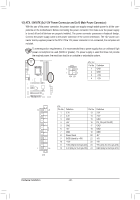
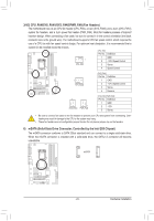
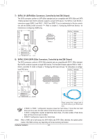
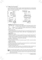
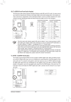
F_AUDIO(H) 3/4/5) CPU_FAN/SYS_FAN1/SYS_FAN2/PWR_FAN (Fan Headers) The motherboard has a 4-pin CPU fan header (CPU_FAN), a 4-pin (SYS_FAN2) and a 3-pin (SYS_FAN1) system fan headers, and a 3-pin power fan header (PWR_FAN). Most fan headers possess a foolproof insertion design. When connecting a fan cable, be sure to connect it in the correct orientation (the black connector wire is the ground wire). The motherboard supports CPU fan speed control, which requires the use of a CPU fan with fan speed control design. For optimum heat dissipation, it is recommended that a system fan be installed inside the chassis. CPU_FAN: Pin No. Definition 1 GND 1 2 +12V /Speed Control CPU_FAN 3 Sense 4 Speed Control 1 SYS_FAN2 SYS_FAN2: Pin No. Definition 1 GND 2 +12V /Speed Control 3 Sense 4 Reserve 1 F_PANEL(NH) 1 SYS_FAN1 PWR_FAN SYS_FAN1/PWR_FAN: Pin No. Definition 1 GNF_DPANEL 2 +1(2HV61M-D2) 3 Sense •• Be sure to connect fan cables to the fan headers to prevent your CPU and system from overheating. Overheating may result in damage to the CPU or the system may hang. •• These fan headers are not configuration jumper blocks. Do not place a jumper cap on the headers. DB_PORT 6) mSATA (Solid-State Drive Connector, Controlled by the Intel Z68 Chipset) The mSATA connector conforms to SATA 3Gb/s standard and can connect to a single solid-state drive. When the mSBAIOTSAScwoitcnhneer (cXt5o8rA-iOsCi)nstalled with a solid-state drive, the SATA2_5 connector will become unavailable. 1 M_SATA mSATA Voltage measurement module(X58A-OC) PWM Switch (X58A-OC) DIP 1 23 1 DIP 1 23 1 DIP 1 23 1 DIP 1 23 PCIe power connector (SATA)(X58A-OC) - 23 - Hardware Installation
-
 1
1 -
2
-
3
-
4
-
5
-
6
-
7
-
8
-
9
-
10
-
11
-
12
-
13
-
14
-
15
-
16
-
17
-
 18
18 -
 19
19 -
 20
20 -
 21
21 -
 22
22 -
 23
23 -
 24
24 -
 25
25 -
 26
26 -
 27
27 -
 28
28 -
29
-
30
-
31
-
32
-
33
-
34
-
35
-
36
-
37
-
38
-
39
-
40
-
41
-
42
-
43
-
44
-
45
-
46
-
47
-
48
-
49
-
50
-
51
-
52
-
53
-
54
-
55
-
56
-
57
-
58
-
59
-
60
-
61
-
62
-
63
-
64
-
65
-
66
-
67
-
68
-
69
-
70
-
71
-
72
-
73
-
74
-
75
-
76
-
77
-
78
-
79
-
80
-
81
-
82
-
83
-
84
-
85
-
86
-
87
-
88
-
89
-
90
-
91
-
92
-
93
-
94
-
95
-
96
-
97
-
98
-
99
-
100
-
101
-
102
-
103
-
104
 |
 |
