Gigabyte GA-Z87X-UD7 TH User Manual - Page 25
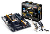
Onboard Voltage Measurement Module, Users can use a multimeter to measure component voltages
 |
View all Gigabyte GA-Z87X-UD7 TH manuals
Add to My Manuals
Save this manual to your list of manuals |
Page 25 highlights
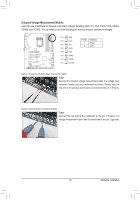
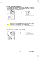
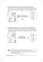
F_USB3F_F _ _ _ 3_ _ 3_ _ 3_ _ 3_ _ 3_ _ 3_ B _U _ S_ _ B _ S B_ B _ B SSSSSS SS F_ _S _S _S _S _S _S _S _S F_ F_ F_ F_ F_ F_ F_ F_ 1 234 1 234 1 234 1 234 1 234 1 234 1 234 1 234 F_USB3F0_USB3F0_USB3F0_USB3F0_USB3F0_USB3F0_USB3F0_USF_B3U0 F_ U F_ U F_ U F_ U F_ U F_ U F_ U S 3 S 3 S 3 S 3 S 3B SS S 3B SSSS B3 SSSS 3B SSS B SSS B SSS UB SSS BU SSS U S U B SS B SS B SS B SS B SS B SS B SS B SS B_ B_ B_ B_ B_ B_ B_ B_ 1 234 1 23 U 1 234 1 234 1 234 1 234 1 234 1 234 1 234 1 234 U 1 23 1 U 1 23 1 234 1 234 1 234 1 234 1 234 1 234 1 234 1 234 1 23 1 1 23 1 1 23 1 1 23 1 1 23 1 1 23 1 1 23 1 1 23 1 1 23 1 234 1 23 1 1 23 1 1 234 1 23 1 1 23 1 1 1 234 1 23 U 1 23 Onboard Voltage Measurement Mo1 dule 1 23 1 1 1 234 1 23 1 23 Users can use a multimeter to measure c1omponent voltages, including VRIN, VIO, VSA, VAXG, VIOA, VRING, 1 23 1 1 1 234 1 23 1 23 VDIMM, and VCORE. You can employ on1 e of the following two ways to measure component voltages. 1 23 1 1 1 234 1 23 1 1 23 1 23 1 234 1 1 1 23 1 1 1 Pin 1 1 Pin 1 Pin 1 VRIN 1 23 VIOD VSA 1 23 1 23 Pin No. Definition 1 Power 2 GND 1 1 Pin 1 VAXG SSSSSS SS Pin 1 VIOA Pin 1 VRING Pin 1 VDIMM Pin 1 VCORE Method I (Using the included voltage measurement cable): Steps: Connect the included voltage measurement cable to a voltage measurement header and your multimeter as shown. Please note the red wire is the positive and must be connected to the pin 1 (Power). Method II (Connecting the multimeter directly): Steps: Connect the red lead of the multimeter to the pin 1 (Power) of a voltage measurement point and the black lead to the pin 2 (ground). - 25 - Hardware Installation
-
 1
1 -
2
-
3
-
4
-
5
-
6
-
7
-
8
-
9
-
10
-
11
-
12
-
13
-
14
-
15
-
16
-
17
-
18
-
19
-
 20
20 -
 21
21 -
 22
22 -
 23
23 -
 24
24 -
 25
25 -
 26
26 -
 27
27 -
 28
28 -
 29
29 -
 30
30 -
31
-
32
-
33
-
34
-
35
-
36
-
37
-
38
-
39
-
40
-
41
-
42
-
43
-
44
-
45
-
46
-
47
-
48
-
49
-
50
-
51
-
52
-
53
-
54
-
55
-
56
-
57
-
58
-
59
-
60
-
61
-
62
-
63
-
64
-
65
-
66
-
67
-
68
-
69
-
70
-
71
-
72
-
73
-
74
-
75
-
76
-
77
-
78
-
79
-
80
-
81
-
82
-
83
-
84
-
85
-
86
-
87
-
88
-
89
-
90
-
91
-
92
-
93
-
94
-
95
-
96
-
97
-
98
-
99
-
100
-
101
-
102
-
103
-
104
-
105
-
106
-
107
-
108
-
109
-
110
-
111
-
112
-
113
-
114
-
115
-
116
-
117
-
118
-
119
-
120
-
121
-
122
-
123
-
124
-
125
-
126
-
127
-
128
 |
 |
