Gigabyte H410M DS2V V2 User Manual - Page 17
COMA Serial Port Header, SPI_TPM Trusted Platform Module Header, CLR_CMOS Clear CMOS Jumper
 |
View all Gigabyte H410M DS2V V2 manuals
Add to My Manuals
Save this manual to your list of manuals |
Page 17 highlights
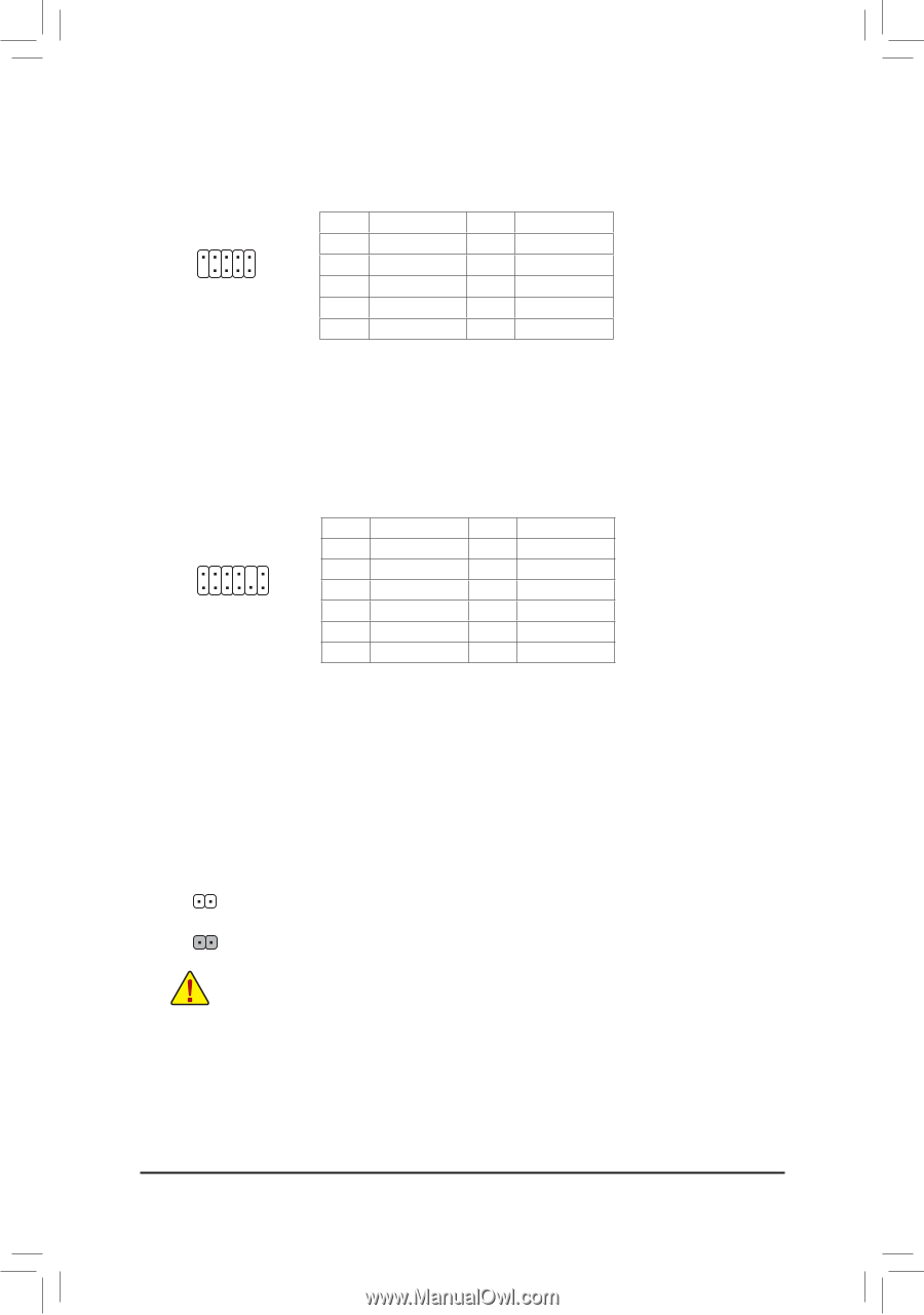
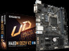
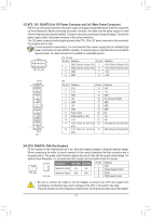
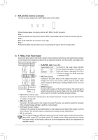
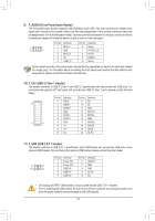
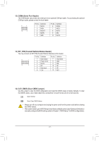
S B_ B S S 12) COMA (Serial Port Header) _ S The COM header can provide one serial port via an optional COM port cable. For purchasing the optional S_ COM port cable, please contact the local dealer. _ B Pin No. Definition Pin No. Definition 9 1 1 NDCD- 6 NDSR- _U _ 10 2 B 2 NSIN 3 NSOUT 4 NDTR- 7 NRTS- 8 F NCTS9 NRI- 5 GND 10 No Pin F_USB3 F _0 _B _ 13) SPI_ST_PM (Trusted Platform Module Header) You may connect an SPI TPM (Trusted Platform Module) to this header. 11 1 12 2 Pin No. 1 2 3 4 5 6 Definition Data Output Power (3.3V) No Pin NC Data Input CLK Pin N_ oF. 7 8 9 10 11 _120 Definition Chip Select GND IRQ NC NC FRST S F_ B_ 14) CLR_CMOS (Clear CMOS Jumper) Use this jumper to clear the BIOS configuration and reset the CMOS values to factory defaults. To clear the CMOS values, use a metal object like a screwdriver to touch the two pins for a few seconds. Open: Normal Short: Clear CMOS Values _3 U •• Always turn off your computer and unplug the power cord from the power outlet before clearing the CMOS values. •• After system restart, go to BIOS Setup to load factory defaults (select Load Optimized Defaults) or manually configure the BIOS settings (refer to Chapter 2, "BIOS Setup," for BIOS configurations). F_USB30 3 - 17 -
-
 1
1 -
2
-
3
-
4
-
5
-
6
-
7
-
8
-
9
-
10
-
11
-
 12
12 -
 13
13 -
 14
14 -
 15
15 -
 16
16 -
 17
17 -
 18
18 -
 19
19 -
 20
20 -
 21
21 -
 22
22 -
23
-
24
-
25
-
26
-
27
-
28
-
29
-
30
-
31
-
32
-
33
-
34
-
35
-
36
-
37
-
38
-
39
-
40
-
41
-
42
-
43
 |
 |