Gigabyte H510M H User Manual - Page 15
SATA3 0/1/2/3 SATA 6Gb/s Connectors, M2A_SB M.2 Socket 3 Connector
 |
View all Gigabyte H510M H manuals
Add to My Manuals
Save this manual to your list of manuals |
Page 15 highlights
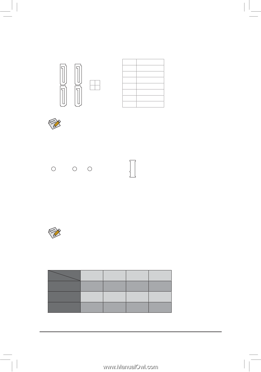
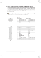
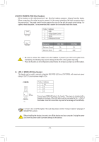
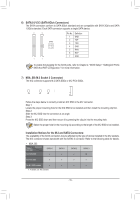
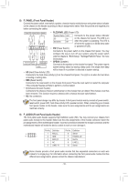
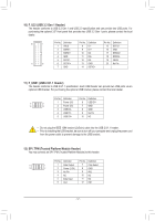
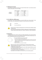
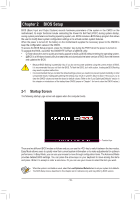
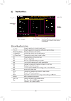
B _U _ B USB3 F S_ F 6) SATA3 0/1/2/3 (SATA 6Gb/s Connectors) The SATA connectors conform to SATA 6Gb/s standard and are compatible with SATA 3Gb/s and SATA 1.5Gb/s standard. Each SATA connector supports a single SATA device. _0 7 7 Pin No. Definition 1 GND SATA3 01 2 3 _F 2 TXP 3 TXN 4 GND 5 RXN 6 RXP 7 GND 1 1 To enable hot-plugging_ f0or theF SATA ports, refer to Chapter 2, "BIOS Setup," "Settings\IO Ports\ SATA And RST Configuration," for more information. 7) M2A_SB (M.2 Socket 3 Connector) The M.2 connector supports M.2 SATA SSDs or M.2 PCIe SSDs. 110 80 60 Follow the steps below to correctly install an M.2 SSD in the M.2 connector. Step 1: Locate the proper mounting hole for the M.2 SSD to be installed and then install the mounting clip first. Step 2: Slide the M.2 SSD into the_c3onnectoUr at an angle. Step 3: Press the M.2 SSD down and then secure it by pressing the clip pin into the mounting hole. Select the proper hole for the mounting clip according to the length of the M.2 SSD to be installed. Installation Notices for the M.2 and SATA Connectors: The availability of the SATA connectors may be affected by the type of device installed in the M.2 sockets. The M.2 connector shares bandwidth with the SATA3 3 connector. Refer to the following table for details. •• M2A_SB: Type of Connector M.2 SSD M.2 SATA SSD SATA3 0 a SATA3 1 a SATA3 2 a SATA3 3 r M.2 PCIe SSD a a a a No M.2 SSD Installed a a a a a: Available, r: Not available - 15 -
-
 1
1 -
2
-
3
-
4
-
5
-
6
-
7
-
8
-
9
-
 10
10 -
 11
11 -
 12
12 -
 13
13 -
 14
14 -
 15
15 -
 16
16 -
 17
17 -
 18
18 -
 19
19 -
 20
20 -
21
-
22
-
23
-
24
-
25
-
26
-
27
-
28
-
29
-
30
-
31
-
32
-
33
-
34
-
35
-
36
-
37
-
38
-
39
-
40
-
41
 |
 |