Gigabyte H610M S2 DDR4 User Manual - Page 20
SATA3 4/5/6/7 SATA 6Gb/s Connectors, M2P_SB M.2 Socket 3 Connector, M.2 PCIe x4 SSD
 |
View all Gigabyte H610M S2 DDR4 manuals
Add to My Manuals
Save this manual to your list of manuals |
Page 20 highlights
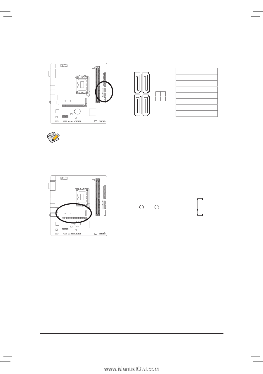
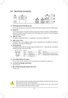
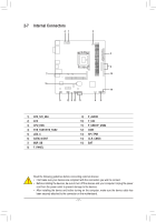
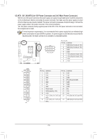
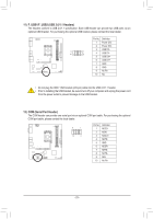
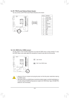
S S __ 3 _ _B _S S_ _ _S DEBUG PORT DEBUG PORT 6) SATA3 4/5/6/B7 (SATA 6Gb/s Connectors) The SATA connectors conform to SATA 6Gb/s standard and are compatible with SATA 3Gb/s and SATA 1.5Gb/s stand_aUrd. Each SATA connector supports a single SATA device. _ F B DEBUG PORT DEBUG PORT F_USB3 F _ S_ 77 11 Pin No. Definition 1 GND 2 TXP SATA3 3 TXN 6 7 _0 4 GND 45 5 RXN 6 RXP 7 GND _F To enable hot-plugging for the SATA ports, please navigate to the "BIOS Setup" page of GIGABYTE's website and search for "SATA Configuration" for more information. _ 7) M2P_SB (M.2 Socket 3 Connector) _0 F The M.2 connector on the motherboard supports only M.2 PCIe SSDs. S F_ B S S_F B_ 80 60 _ F_USB3 Follow the steps below to correctly install an M.2 SSD in the M.2 connector. Step 1: _3 U Locate the proper mounting hole for the M.2 SSD to be installed and then install the mounting clip first. Step 2: Slide the M.2 SSD into the connector at an angle. Step 3: Press the M.2 SSD down and then secure it by pressing the clip pin into the mounting hole. * Types of M.2 SSDs supported by each M.2 connector: F_USB30 3 M.2 PCIe x4 SSD M.2 PCIe x2 SSD M2P_SB a a M.2 SATA SSD r - 20 -
-
 1
1 -
2
-
3
-
4
-
5
-
6
-
7
-
8
-
9
-
10
-
11
-
12
-
13
-
14
-
 15
15 -
 16
16 -
 17
17 -
 18
18 -
 19
19 -
 20
20 -
 21
21 -
 22
22 -
 23
23 -
 24
24 -
 25
25 -
26
-
27
-
28
-
29
-
30
 |
 |