Gigabyte MB10-DS1 Manual
Gigabyte MB10-DS1 Manual
 |
View all Gigabyte MB10-DS1 manuals
Add to My Manuals
Save this manual to your list of manuals |
Gigabyte MB10-DS1 manual content summary:
- Gigabyte MB10-DS1 | Manual - Page 1
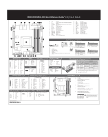
MB10-DS0/MB10-DS1 Quick Reference Guide 35 34 33 23 4 5 6 78 9 No. Code Description 1 CPU Intel Xeon® processor D-1541, FCBGA1667 SoC (MB10-DS0) Intel Xeon® processor D-1521, FCBGA1667 SoC (MB10-DS1) 2 LAN1_2 LAN ports 3 USB3_MLAN BMC Management LAN port (top) / USB 3.0 ports ( - Gigabyte MB10-DS1 | Manual - Page 2
contact your local government office, your household waste disposal service or where you purchased the product for details of product's user's manual and we will be glad to help you with your effort. Restriction of Hazardous Substances (RoHS) Directive Statement GIGABYTE products have not
-
 1
1 -
 2
2
 |
 |
1
2
3
4
5
6
7
8
9
10
11
12
13
14
15
18
17
16
19
20
21
22
24
23
25
26
27
28
30
29
31
32
33
34
35
Front Panel Header/
前面板
HDD Back Plane Board Header/
硬盤背板排針
ATX Power/
电源
PMBUS
Memory Popula°on Configura°on/
安装内存
Type
Ranks PerDIMM
and
Data Width
Speed (MT/s);
Slot Per Channel (SPC) and DIMM Per Channel (DPC)
RDIMM
RDIMM
RDIMM
RDIMM
SRx4 ECC
1600, 1866, 2133
1600, 1866, 2133
1600, 1866, 2133
1600, 1866, 2133
1600, 1866, 2133
1600, 1866, 2133
1600, 1866, 2133
1600, 1866, 2133
1600, 1866, 2133
1600, 1866, 2133
1600, 1866, 2133
1600, 1866, 2133
1 Slot Per Channel
1DPC
2 Slot Per Channel
1DPC
2DPC
SRx8 ECC
DRx8 ECC
DRx4 ECC
Rear I/O Connector
/
后面板接口
SATA Connector/SATA
接口
No.
Pin Define
1
GND
2
TXP
3
TXN
4
GND
No.
Pin Define
5
RXN
6
RXP
7
GND
7
SATA SGPIO Header/
串行
GPIO
5
1
NVME Connector
4
1
No.
Pin Define
1
GND
2
SMBUS Data
3
SMBUS Clock
4
GND
1
2
13
14
TPM Connector/
可信平台模块
BMC F/W Readiness LED
CPU/System FAN/
风扇
1
4
1
4
IPMB
Jumper Se±ngs/
跳线设置
1
5
2
3
4
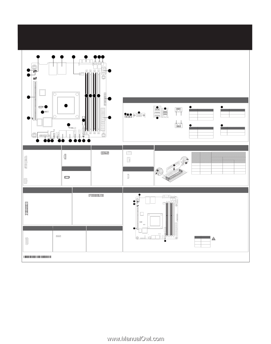
只使用一个DIMM时,必须安装到内存插槽0。
若安装顺序有误,系统将不能正常引导。
1
2
2
3
1
3
4
7
6
5
No.
Pin Define
1
CLK
2
P_3V3_AUX
3
LPC_RST
4
P3V3
5
LPC_LAD0
6
IRQ_SERIAL
7
LPC_LAD1
8
No Connect
9
LPC_LAD2
10
No Connect
11
LPC_LAD3
12
GND
13
LPC_FRAME_N
14
GND
No.
Pin Define
1
SDIN
2
GND
3
SDOUT
4
SLOAD
5
SCLK
MB10-DS0/MB10-DS1 Quick Reference Guide/
快速测试参考指南
1
5
1
3
1
8
4
5
1
24
1
1
2
23
1
2
25
26
No.
Pin Define
1
3.3V
2
3.3V
3
GND
4
+5V
5
GND
6
+5V
7
GND
8
Power Good
9
5VSB
10
+12V
11
+12V
12
3.3V
No.
Pin Define
1
GND
2
GND
3
GND
4
GND
No.
Pin Define
1
PMBus Clock
2
PMBus Data
3
PMBus Alert
4
GND
5
3.3V Sense
No.
Pin Define
1
Clock
2
GND
3
Data
No.
Code
Descrip°on
1
CPU
Intel Xeon® processor D-1541, FCBGA1667 SoC (MB10-DS0)
Intel Xeon® processor D-1521, FCBGA1667 SoC (MB10-DS1)
2
LAN1_2
LAN ports
3
USB3_MLAN
BMC Management LAN port (top) / USB 3.0 ports (bo±om)
4
CPU0_FAN
CPU fan connector
5
VGA
VGA port
6
SW_ID
ID switch bu±on w/LED
7
SW_PWR
Power bu±on w/LED
8
LED_STA
System Status LED
9
P12V_AUX2
8 pin power connector
10
FP_1
Front panel header
11
ATX1
24 pin main power connector
12
DIMM_P0_A0
Channel 1 slot 0
13
DIMM_P0_A1
Channel 2 slot 1
14
DIMM_P0_B0
Channel 3 slot 0
15
DIMM_P0_B1
Channel 4 slot 1
16
BAT1
Ba±ery
17
PMBUS
PMBus connector
18
SATA_DOM0
SATA port 0 DOM support jumper
No.
Pin Define
1
Power LED+
3
No Pin
5
Power LED-
7
HDD LED+
9
HDD LED-
11
Power Bu±on
13
GND
15
Reset Bu±on+
17
GND
19
ID Switch+
21
ID Switch-
23
NMI Switch-
No.
Desrip°on
1
System Status LED
2
Power bu±on w/LED
3
ID switch bu±on w/LED
4
VGA port
5
USB 3.0 ports
6
KVM Server Management 10/100/1000 LAN Port (Dedicated LAN Port)
7
LAN ports
No.
Desrip°on
1
Clear CMOS Jumper
1-2 Close: Normal opera°on (Default se²ng)
2-3 Close: Clear CMOS data.
2
ME Update Jumper
1-2 Close: ME update.
2-3 Close: Normal opera°on (Default se²ng)
3
ME Recovery Jumper
1-2 Close: Normal opera°on. (Default se²ng)
2-3 Close: ME recovery mode.
4
S3 Power On Select Jumper
1-2 Close: Stop an ini°al power on when BMC is not ready.
2-3 Close: Keep ini°al power on. (Default se²ng)
5
SATA Port 0 DOM Support Jumper Jumper
1-2 Close: Enable SATA port DOM support fun°on.
2-3 Close: Normal Opera°on. (Default se²ng)
When only
one DIMM is used, it must be populated in memory slot0 first.
System will not boot normally with incorrect populated sequence.
If a SATA type hard drive is connected to the
motherboard, please ensure the jumper is
closed and set to 2-3 pins (Default se²ng),
in order to reduce any risk of hard disk
damage.
Speed LED
Power bu±on/LED:
Off
State
Description
Yellow On
1Gbps data arte
Green On
100Mbps data arte
10Mbps data arte
7
10/100/1000 LAN LED:
Link/Ac°vity
LED
13
12
24
No.
Code
Descrip°on
19
SATA0
SATA 3 6Gb/s connector
20
SATA1
SATA 3 6Gb/s connector
21
SATA_2_3
SATA 3 6Gb/s connectors
22
SATA_4_5
SATA 3 6Gb/s connectors
23
SATA_SGPIO
SATA SGPIO header
24
SYS_FAN2
System fan connector#2
25
COM2
Serial port cable connector
26
LED_BMC1
BMC firmware readiness LED
27
BP_1
HDD back plane board header
28
NVME_PH
NVME connector
29
TPM
TPM module connector
30
IPMB
IPMB connector
31
CLR_CMOS
Clear CMOS jumper
32
PCIE_1
PCI Express x16 slot
33
ME_UPDATE
ME update jumper
34
ME_RCVR
ME recovry jumper
35
S3_MASK
S3 Power On Select jumper
Green On
Off
Description
System is powered on
System is powered off
State
ID switch bu±on w/LED:
Blue On
Off
Description
Unit selected for identification
No identification
State
System Status LED:
Green On
Amber On
Off
Description
Normal operation
Critical alert.
System is not ready
State
No.
Pin Define
13
3.3V
14
-12V
15
GND
16
PS_ON
17
GND
18
GND
19
GND
20
-5V
21
+5V
22
+5V
23
+5V
24
GND
No.
Pin Define
5
+12V
6
+12V
7
+12V
8
+12V
No.
Pin Define
2
5V Standby
4
ID LED+
6
ID LED-
8
System Front Board LED+
10
System Status LED-
12
LAN1 Ac°ve LED+
14
LAN1 Link LED-
16
SMBus Data
18
SMBus Clock
20
Case Open
22
LAN2 Ac°ve LED
24
LAN2 Link LED-
No.
Pin Define
1
BP_SGP_CLK
3
BP_SGP_GLD
5
BP_SGP_DOUT
7
Key Pin
9
GND
11
BP_LED_G_N
13
BP_SGP_DIN
15
GND
17
GND
19
P_3V3_AUX
21
P_3V3_AUX
23
GND
25
BP_PRESENSE
No.
Pin Define
2
No Connect
4
FAN_SGP_GLD
6
GND
8
Reset
10
BP_LED_A_N
12
GND
14
No Connect
16
SMB_BP_DATA
18
SMB_BP_CLK
20
BMC_ACK
22
BMC_REQ
24
Key Pin
26
GND
No.
Pin Define
1
GND
2
+12V
3
Sense
4
Speed Control
1
2
Definition
P5V
SATA0 Pin 8
3
GND
Pin No.
State
Descrip°on
On
BMC firmware is ini°al
Blink
BMC
firmware is ready
Off
AC loss
BMC Firmware Readiness LED (LED_BMC1):
12QM1-MB10D0-00R