Gigabyte MB10-DS1 Manual - Page 1
Gigabyte MB10-DS1 Manual
 |
View all Gigabyte MB10-DS1 manuals
Add to My Manuals
Save this manual to your list of manuals |
Page 1 highlights
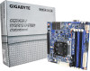
MB10-DS0/MB10-DS1 Quick Reference Guide 35 34 33 23 4 5 6 78 9 No. Code Description 1 CPU Intel Xeon® processor D-1541, FCBGA1667 SoC (MB10-DS0) Intel Xeon® processor D-1521, FCBGA1667 SoC (MB10-DS1) 2 LAN1_2 LAN ports 3 USB3_MLAN BMC Management LAN port (top) / USB 3.0 ports (bottom) 4 CPU0_FAN CPU fan connector 5 VGA VGA port 6 SW_ID ID switch button w/LED 7 SW_PWR Power button w/LED 8 LED_STA System Status LED 9 P12V_AUX2 8 pin power connector 10 FP_1 Front panel header 11 ATX1 24 pin main power connector 12 DIMM_P0_A0 Channel 1 slot 0 13 DIMM_P0_A1 Channel 2 slot 1 14 DIMM_P0_B0 Channel 3 slot 0 15 DIMM_P0_B1 Channel 4 slot 1 16 BAT1 Battery 17 PMBUS PMBus connector 18 SATA_DOM0 SATA port 0 DOM support jumper No. Code Description 19 SATA0 SATA 3 6Gb/s connector 20 SATA1 SATA 3 6Gb/s connector 21 SATA_2_3 SATA 3 6Gb/s connectors 22 SATA_4_5 SATA 3 6Gb/s connectors 23 SATA_SGPIO SATA SGPIO header 24 SYS_FAN2 System fan connector#2 25 COM2 Serial port cable connector 26 LED_BMC1 BMC firmware readiness LED 27 BP_1 HDD back plane board header 28 NVME_PH NVME connector 29 TPM TPM module connector 30 IPMB IPMB connector 31 CLR_CMOS Clear CMOS jumper 32 PCIE_1 PCI Express x16 slot 33 ME_UPDATE ME update jumper 34 ME_RCVR ME recovry jumper 35 S3_MASK S3 Power On Select jumper 32 30 29 31 1 23 15 14 13 12 10 11 16 28 27 26 25 24 22 21 20 19 18 17 Rear I/O Connector 12 3 4 6 7 1 System Status LED: State Description Green On Normal operation Amber On Critical alert. 5 Speed LED Link/Activity LED Off System is not ready No. Desription 1 System Status LED 2 Power button w/LED 3 ID switch button w/LED 4 VGA port 5 USB 3.0 ports 6 KVM Server Management 10/100/1000 LAN Port (Dedicated LAN Port) 7 LAN ports 7 10/100/1000 LAN LED: State Yellow On Description 1Gbps data arte Green On 100Mbps data arte Off 10Mbps data arte 2 Power button/LED: State Green On Description System is powered on Off System is powered off 3 ID switch button w/LED: State Description Blue On Unit selected for identification Off No identification ATX Power/ 䕚๕ No. 1 13 1 2 3 4 5 6 7 8 9 24 12 10 11 12 Pin Define No. 3.3V 13 3.3V 14 GND 15 +5V 16 GND 17 +5V 18 GND 19 Power Good 20 5VSB 21 +12V 22 +12V 23 3.3V 24 Pin Define 3.3V -12V GND PS_ON GND GND GND -5V +5V +5V +5V GND 4 8 No. 1 2 3 15 4 Pin Define No. GND 5 GND 6 GND 7 GND 8 Pin Define +12V +12V +12V +12V PMBUS 1 No. Pin Define 1 PMBus Clock 2 PMBus Data 3 PMBus Alert 4 GND 5 5 3.3V Sense IPMB No. Pin Define 1 Clock 3 12 GND 3 Data TPM Connector 2 14 1 13 No. Pin Define 1 CLK 2 P_3V3_AUX 3 LPC_RST 4 P3V3 5 LPC_LAD0 6 IRQ_SERIAL 7 LPC_LAD1 8 No Connect 9 LPC_LAD2 10 No Connect 11 LPC_LAD3 12 GND 13 LPC_FRAME_N 14 GND CPU/System FAN/ 䔎ࣂ 4 1 No. 4 1 2 3 4 1 Pin Define GND +12V Sense Speed Control NVME Connector 1 No. 1 2 3 44 Pin Define GND SMBUS Data SMBUS Clock GND Front Panel Header No. 24 23 1 3 5 7 9 11 13 15 17 2 1 19 21 23 Pin Define No. Power LED+ 2 No Pin 4 Power LED- 6 HDD LED+ 8 HDD LED- 10 Power Button 12 GND 14 Reset Button+ 16 GND 18 ID Switch+ 20 ID Switch- 22 NMI Switch- 24 Pin Define 5V Standby ID LED+ ID LEDSystem Front Board LED+ System Status LEDLAN1 Active LED+ LAN1 Link LEDSMBus Data SMBus Clock Case Open LAN2 Active LED LAN2 Link LED- HDD Back Plane Board Header 26 25 No. Pin Define 1 BP_SGP_CLK 3 BP_SGP_GLD 5 BP_SGP_DOUT 7 Key Pin 9 GND 11 BP_LED_G_N 13 BP_SGP_DIN 15 GND 17 GND 19 P_3V3_AUX 21 P_3V3_AUX 23 GND 25 BP_PRESENSE 1 2 No. Pin Define 2 No Connect 4 FAN_SGP_GLD 6 GND 8 Reset 10 BP_LED_A_N 12 GND 14 No Connect 16 SMB_BP_DATA 18 SMB_BP_CLK 20 BMC_ACK 22 BMC_REQ 24 Key Pin 26 GND 4 3 2 SATA Connector/SATA 接口 SATA SGPIO Header/ ЕБ GPIO BMC F/W Readiness LED 1 No. Pin Define 1 GND 7 2 TXP 3 TXN 4 GND No. Pin Define 1 5 RXN 6 RXP 7 GND No. Pin Define 1 SDIN 1 5 2 GND 3 SDOUT 4 SLOAD 5 SCLK BMC Firmware Readiness LED (LED_BMC1): State On Blink Off Description BMC firmware is initial BMC firmware is ready AC loss 12QM1-MB10D0-00R Memory Population Configuration Type Ranks PerDIMM and Data Width Speed (MT/s); Slot Per Channel (SPC) and DIMM Per Channel (DPC) 1 Slot Per Channel 2 Slot Per Channel 1DPC 1DPC 2DPC RDIMM RDIMM SRx4 ECC SRx8 ECC 1600, 1866, 2133 1600, 1866, 2133 1600, 1866, 2133 1600, 1866, 2133 1600, 1866, 2133 1600, 1866, 2133 RDIMM DRx8 ECC 1600, 1866, 2133 1600, 1866, 2133 1600, 1866, 2133 RDIMM DRx4 ECC 1600, 1866, 2133 1600, 1866, 2133 1600, 1866, 2133 When only one DIMM is used, it must be populated in memory slot0 first. System will not boot normally with incorrect populated sequence. DIMM 0 Jumper Settings No. Desription 1 Clear CMOS Jumper 1-2 Close: Normal operation (Default setting) 2-3 Close: Clear CMOS data. 2 ME Update Jumper 1-2 Close: ME update. 2-3 Close: Normal operation (Default setting) 3 ME Recovery Jumper 1-2 Close: Normal operation. (Default setting) 2-3 Close: ME recovery mode. 4 S3 Power On Select Jumper 1-2 Close: Stop an initial power on when BMC is not ready. 2-3 Close: Keep initial power on. (Default setting) 5 SATA Port 0 DOM Support Jumper Jumper 1-2 Close: Enable SATA port DOM support funtion. 2-3 Close: Normal Operation. (Default setting) Pin No. Definition If a SATA type hard drive is connected to the 5 1 P5V motherboard, please ensure the jumper is closed and set to 2-3 pins (Default setting), 2 SATA0 Pin 8 in order to reduce any risk of hard disk damage. 3 GND
-
 1
1 -
 2
2
 |
 |