Gigabyte MB10-DS5 Manual - Page 1
Gigabyte MB10-DS5 Manual
 |
View all Gigabyte MB10-DS5 manuals
Add to My Manuals
Save this manual to your list of manuals |
Page 1 highlights
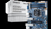
MB10-DS Series Quick Reference Guide 36 2 3 4 5 6 789 35 10 34 33 31 30 32 16 15 14 13 11 1 17 12 24 29 28 27 26 25 23 22 21 20 19 18 No. Code Description No. Code Description 1 CPU Intel Xeon® processor D-1541, FCBGA1667 SoC (MB10-DS0/3) 20 SATA0 SATA 3 6Gb/s connector Intel Xeon® processor D-1521, FCBGA1667 SoC (MB10-DS1/4) 21 SATA1 SATA 3 6Gb/s connector Intel Xeon® processor D-1581, FCBGA1667 SoC (MB10-DS2/5) 22 SATA_2_3 SATA 3 6Gb/s connectors 2 SFP+1_2 SFP+ LAN connectors#1/#2 23 SATA_4_5 SATA 3 6Gb/s connectors 3 LAN1_2 LAN ports 24 SATA_SGPIO SATA SGPIO header 4 USB3_MLAN BMC Management LAN port (top) / USB 3.0 ports (bottom) 25 SYS_FAN 2 System fan connector#2 5 CPU0_FAN CPU fan connector 26 COM1 Serial port cable connector 6 VGA VGA port 27 LED_BMC1 BMC firmware readiness LED 7 SW_ID ID switch button w/LED 28 BP_1 HDD back plane board header 8 SW_PWR Power button w/LED 29 NVME_PH NVME connector 9 LED_STA System Status LED 30 TPM TPM module connector 10 P12V_AUX2 8 pin power connector 31 IPMB IPMB connector 11 FP_1 Front panel header 32 CLR_CMOS Clear CMOS jumper 12 ATX1 24 pin main power connector 33 PCIE_1 PCI Express x16 slot 13 DIMM_P0_A0 Channel 1 slot 0 34 ME_UPDATE ME update jumper 14 DIMM_P0_A1 Channel 2 slot 1 35 ME_RCVR ME recovry jumper 15 DIMM_P0_B0 Channel 3 slot 0 36 S3_MASK S3 Power On Select jumper 16 DIMM_P0_B1 Channel 4 slot 1 17 BAT1 Battery 18 PMBUS PMBus connector 19 SATA_DOM0 SATA DOM power cable connector Rear I/O Connector 1 4 23 6 7 8 5 10/100/1000 LAN LED: State Description Speed LED Link/Activity LED Yellow On Green On 1Gbps data arte 100Mbps data arte Off 10Mbps data arte No. Desription 1 System Status LED 2 Power button w/LED Speed LED Link/Activity LED SFP+ LAN LED: 3 ID switch button w/LED State Description 4 VGA port 5 USB 3.0 ports Yellow On 1Gbps data rate 6 KVM Server Management 10/100/1000 LAN Port (Dedicated LAN Port) Green On 10 Gbps data rate 7 LAN ports 8 SFP+ LAN ports (MB10-DS3/MB10-DS4/MB10-DS5) System Status LED: State Description Green On Normal operation Amber On Critical alert. Off System is not ready Power button/LED: State Green On Description System is powered on Off System is powered off ID switch button w/LED: State Description Blue On Unit selected for identification Off No identification ATX Power/ 䕚๕ No. Pin Define No. Pin Define 1 3.3V 13 3.3V 1 13 1 2 3.3V 3 GND 14 -12V 15 GND 4 +5V 16 PS_ON 5 GND 17 GND 5 6 +5V 18 GND 7 GND 19 GND 8 Power Good 20 -5V 9 5VSB 21 +5V 24 12 10 11 +12V +12V 22 +5V 23 +5V 12 3.3V 24 GND 4 8 No. Pin Define No. Pin Define 3 1 GND 5 +12V 2 GND 6 +12V 3 GND 7 +12V 4 GND 15 8 +12V Front Panel Header PMBUS No. Pin Define 1 PMBus Clock 2 PMBus Data 3 PMBus Alert 4 GND 5 3.3V Sense IPMB No. 1 12 3 Pin Define Clock GND Data TPM Connector CPU/System FAN/ 䔎ࣂ 2 14 1 13 No. Pin Define 1 CLK 2 P_3V3_AUX 3 LPC_RST 4 P3V3 5 LPC_LAD0 6 IRQ_SERIAL 7 LPC_LAD1 8 No Connect 9 LPC_LAD2 10 No Connect 11 LPC_LAD3 12 GND 13 LPC_FRAME_N 14 GND 4 1 No. 4 1 2 3 4 1 Pin Define GND +12V Sense Speed Control NVME Connector 1 No. 1 2 3 44 Pin Define GND SMBUS Data SMBUS Clock GND HDD Back Plane Board Header No. 24 23 1 3 5 7 9 11 13 15 17 2 1 19 21 23 Pin Define No. Power LED+ 2 No Pin 4 Power LED- 6 HDD LED+ 8 HDD LED- 10 Power Button 12 GND 14 Reset Button+ 16 GND 18 ID Switch+ 20 ID Switch- 22 NMI Switch- 24 Pin Define 5V Standby ID LED+ ID LEDSystem Status LED+ System Status LEDLAN1 Active LED+ LAN1 Link LEDSMBus Data SMBus Clock Case Open LAN2 Active LED LAN2 Link LED- 26 25 No. Pin Define 1 BP_SGP_CLK 3 BP_SGP_GLD 5 BP_SGP_DOUT 7 Key Pin 9 GND 11 BP_LED_G_N 13 BP_SGP_DIN 15 GND 17 GND 19 P_3V3_AUX 21 P_3V3_AUX 23 GND 25 BP_PRESENSE 1 2 No. Pin Define 2 No Connect 4 FAN_SGP_GLD 6 GND 8 Reset 10 BP_LED_A_N 12 GND 14 No Connect 16 SMB_BP_DATA 18 SMB_BP_CLK 20 BMC_ACK 22 BMC_REQ 24 Key Pin 26 GND 4 3 2 SATA Connector/SATA 接口 BMC F/W Readiness LED Serial Port Cable Connector 7 No. 1 2 3 14 Pin Define No. GND 5 TXP 6 TXN 7 GND Pin Define RXN RXP GND BMC Firmware Readiness LED (LED_BMC1): State Description On BMC firmware is initial Blink BMC firmware is ready Off AC loss No. Pin Define 12 1 NDCD- 2 NSIN 3 NSOUT 4 NDTR- 9 10 5 GND 1 6 NDSR- SATA SGPIO Header/ ЕБ GPIO SATA DOM Power Cable Connector 7 NRTS8 NCTS- No. Pin Define No. Pin Define No. Pin Define 1 1 52 SDIN 4 GND 5 SLOAD 3 1 SCLK 1 P5V 2 GND 3 SDOUT 3 NC 9 NRI10 No Pin 12QM1-MB10D0-00R Memory Population Configuration Type RDIMM Ranks PerDIMM and Data Width Speed (MT/s); Slot Per Channel (SPC) and DIMM Per Channel (DPC) 1 Slot Per Channel 2 Slot Per Channel 1DPC 1DPC 2DPC SRx4 ECC 1600, 1866, 2133, 2400* 1600, 1866, 2133, 2400* 1600, 1866, 2133, 2400* RDIMM RDIMM RDIMM SRx8 ECC DRx8 ECC DRx4 ECC 1600, 1866, 2133, 2400* 1600, 1866, 2133, 2400* 1600, 1866, 2133, 2400* 1600, 1866, 2133, 2400* 1600, 1866, 2133, 2400* 1600, 1866, 2133, 2400* 1600, 1866, 2133, 2400* 1600, 1866, 2133, 2400* 1600, 1866, 2133, 2400* Note: DDR4 2400MHz is only available on Intel Xeon® D-1541 processor. When only one DIMM is used, it must be populated in memory slot0 first. System will not boot normally with incorrect populated sequence. 仅Intel Xeon® D-1541 DDR4-2400MHz内存。 DIMM 0。 Jumper Settings No. Desription 1 Clear CMOS Jumper 1-2 Close: Normal operation (Default setting) 2-3 Close: Clear CMOS data. 2 ME Update Jumper 1-2 Close: ME update. 2-3 Close: Normal operation (Default setting) 3 ME Recovery Jumper 1-2 Close: Normal operation. (Default setting) 2-3 Close: ME recovery mode. 4 S3 Power On Select Jumper 1-2 Close: Stop an initial power on when BMC is not ready. 2-3 Close: Keep initial power on. (Default setting)
-
 1
1 -
 2
2
 |
 |
