Gigabyte MD60-SC0 Manual - Page 8
BMC Management LAN port link LED header
 |
View all Gigabyte MD60-SC0 manuals
Add to My Manuals
Save this manual to your list of manuals |
Page 8 highlights
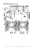
42 SAS0~7 43 SAS_SGP2 44 RAID_SLOT2 45 BAT 46 SATA_DOM4 47 SATA5 48 SATA4 49 SATA_DOM5 50 CPU0_FAN 51 CLR_CMOS 52 SAS_SGP1 53 MINI_CN1 54 MINI_CN2 55 RAID_SLOT1 56 CASE_OPEN 57 ME_UPDATE 58 BIOS_PWD 59 BIOS_RCVR 60 ME_RCVR 61 S3_MASK 62 SW_RAID 63 PCIE_1 64 PCIE_2 65 PCIE_3 66 PCIE_4 67 MLAN_LINK 68 MLAN_ACT 69 IPMB 70 BMC_FRB 71 TPM SAS 6Gb/s connectors (Gigabyte extension card required) SAS SGPIO header#2 PCI Express x4 slot (Proprietary slot) Battery socket SATA port 4 DOM support jumper SATA 3 6Gb/s connector SATA 3 6Gb/s connector SATA port 5 DOM support jumper CPU0 fan connector (for Primary CPU) Clear CMOS jumper SAS SGPIO header#1 Mini-SAS cable connector#1 supports SATA3 6Gb/s Mini-SAS cable connector#2 supports SATA3 6Gb/s PCI Express x8 slot Case open intrusion alert header ME update jumper Clearing Supervisor Password jumper BIOS recovery jumper ME recovery jumper S3 Power On Select jumper Intel/LSI Software RAID Key jumper PCI Express x16 slot PCI Express x8 slot (Shared bandwidth with PCIE_3) PCI Express x16 slot PCI Express x8 slot BMC Management LAN port link LED header BMC Management LAN port active LED header IPMB connector Force to Stop FRB Timer jumper TPM module connector CAUTION! If a SATA type hard drive is connected to the motherboard, please ensure the jumper is closed and set to 2-3 pins (Default setting), in order to reduce any risk of hard disk damage. Please refer to Page 35 for SATA_DOM4 and SATA_DOM5 jumper setting instruction. - 8 -
-
 1
1 -
2
-
 3
3 -
 4
4 -
 5
5 -
 6
6 -
 7
7 -
 8
8 -
 9
9 -
 10
10 -
 11
11 -
 12
12 -
 13
13 -
14
-
15
-
16
-
17
-
18
-
19
-
20
-
21
-
22
-
23
-
24
-
25
-
26
-
27
-
28
-
29
-
30
-
31
-
32
-
33
-
34
-
35
-
36
-
37
-
38
-
39
-
40
-
41
-
42
-
43
-
44
-
45
-
46
-
47
-
48
-
49
-
50
-
51
-
52
-
53
-
54
-
55
-
56
-
57
-
58
-
59
-
60
-
61
-
62
-
63
-
64
-
65
-
66
-
67
-
68
-
69
-
70
-
71
-
72
-
73
-
74
-
75
-
76
-
77
-
78
-
79
-
80
-
81
-
82
-
83
-
84
-
85
-
86
-
87
-
88
-
89
-
90
-
91
-
92
-
93
-
94
-
95
-
96
-
97
-
98
-
99
-
100
-
101
-
102
-
103
-
104
-
105
-
106
-
107
-
108
-
109
-
110
-
111
-
112
-
113
-
114
-
115
-
116
-
117
-
118
-
119
-
120
-
121
-
122
-
123
-
124
-
125
-
126
-
127
 |
 |