Gigabyte MD80-TM1 Manual - Page 1
Gigabyte MD80-TM1 Manual
 |
View all Gigabyte MD80-TM1 manuals
Add to My Manuals
Save this manual to your list of manuals |
Page 1 highlights
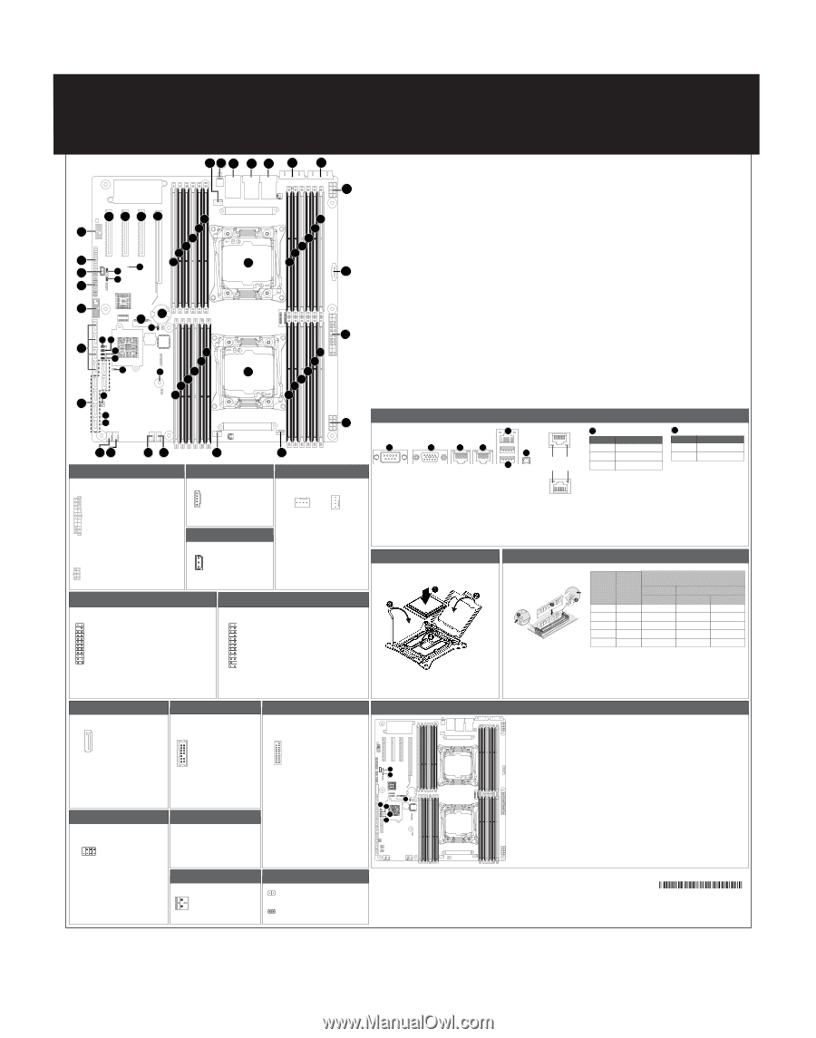
MD80-TM1 Quick Reference Guide 12 3 4 5 6 7 8 53 54 55 56 69 52 68 67 66 65 51 64 57 50 58 59 49 10 11 12 13 14 16 15 9 48 63 62 61 17 46 45 47 44 28 18 43 29 19 42 60 30 31 32 26 20 21 22 41 33 23 40 39 38 24 37 36 35 34 27 25 ATX Power/ 䕚๕ No. 1 13 1 2 3 4 5 6 7 8 9 24 12 10 11 12 Pin Define No. 3.3V 13 3.3V 14 GND 15 +5V 16 GND 17 +5V 18 GND 19 Power Good 20 5VSB 21 +12V 22 +12V 23 3.3V 24 Pin Define 3.3V -12V GND PS_ON GND GND GND -5V +5V +5V +5V GND 5 1 No. 1 2 3 84 4 Pin Define No. GND 5 GND 6 GND 7 GND 8 Pin Define +12V +12V +12V +12V PMBUS 5 No. Pin Define 1 PMBus Clock 2 PMBus Data 3 PMBus Alert 4 GND 1 5 3.3V Sense IPMB 1 No. Pin Define 1 Clock 2 GND 3 Data 3 CPU/System FAN/ 䔎ࣂ 4 4 1 1 No. Pin Define 1 GND 2 +12V 3 Sensor 4 Speed Control Front Panel Header No. 12 1 3 5 7 9 11 13 15 23 24 17 19 21 23 Pin Define No. Power LED+ 2 No Pin 4 Power LED- 6 HDD LED+ 8 HDD LED- 10 Power Button 12 GND 14 Reset Button+ 16 GND 18 ID Switch+ 20 ID Switch- 22 NMI Switch- 24 Pin Define 5V Standby ID LED+ ID LEDSystem Status LED (Green) System Status LED (Amber) LAN1 Active LED+ LAN1 Link LEDSMBus Data SMBus Clock Case Open LAN2 Active LED LAN2 Link LED- HDD Back Plane Board Header No. 12 1 3 5 7 9 11 13 15 17 25 26 19 21 23 25 Pin Define No. BP_SGP_CLK 2 BP_SGP_GLD 4 BP_SGP_DOUT 6 Key Pin 8 GND 10 BP_LED_G_N 12 BP_SGP_DIN 14 GND 16 GND 18 P_3V3_AUX 20 P_3V3_AUX 22 GND 24 BP_PRESENSE 26 Pin Define No Connect FAN_SGP_GLD GND Reset BP_LED_A_N GND No Connect SMB_BP_DATA SMB_BP_CLK BMC_ACK BMC_REQ Key Pin GND No. Code Description 1 CPU1_FAN CPU1 fan connector (for Secondary CPU) 2 SW_ID ID switch button 3 USB3_MLAN BMC Management LAN port (top) / USB 3.0 ports (bottom) 4 LAN1 LAN port #1 5 LAN2 LAN port #2 6 VGA VGA port 7 COM1 Serial port 8 P12V_AUX2 8 pin power connector (for secondary CPU) 9 PMBUS PMBus connector 10 DIMM_P1_G0 Channel 3 slot 0 (for secondary CPU) 11 DIMM_P1_G1 Channel 3 slot 1 (for secondary CPU) 12 DIMM_P1_G2 Channel 3 slot 2 (for secondary CPU) 13 DIMM_P1_H0 Channel 4 slot 0 (for secondary CPU) 14 DIMM_P1_H1 Channel 4 slot 1 (for secondary CPU) 15 DIMM_P1_H2 Channel 4 slot 2 (for secondary CPU) 16 CPU1 Intel LGA2011 Socket R (Secondary CPU) 17 ATX1 24 pin main power connector 18 DIMM_P0_A0 Channel 1 slot 0 (for primary CPU) 19 DIMM_P0_A1 Channel 1 slot 1 (for primary CPU) 20 DIMM_P0_A2 Channel 1 slot 2 (for primary CPU) 21 DIMM_P0_B0 Channel 2 slot 0 (for primary CPU) 22 DIMM_P0_B1 Channel 2 slot 1 (for primary CPU) 23 DIMM_P0_B2 Channel 2 slot 2 (for primary CPU) 24 P12V_AUX1 8 pin power connector (for primary CPU) 25 SYS_FAN5 System fan connector#5 26 CPU0 Intel LGA2011 Socket R (Primary CPU) 27 CPU0_FAN CPU0 fan connector (for Primary CPU) 28 DIMM_P0_D2 Channel 4 slot 2 (for primary CPU) 29 DIMM_P0_D1 Channel 4 slot 1 (for primary CPU) 30 DIMM_P0_D0 Channel 4 slot 0 (for primary CPU) 31 DIMM_P0_C2 Channel 3 slot 2 (for primary CPU) 32 DIMM_P0_C1 Channel 3 slot 1 (for primary CPU) 33 DIMM_P0_C0 Channel 3 slot 0 (for primary CPU) 34 SYS_FAN4 System fan connector#4 35 SYS_FAN3 System fan connector#3 No. Code Description 36 SYS_FAN2 System fan connector#2 37 SYS_FAN1 System fan connector#1 38 SSATA_SGP sSATA SGPIO header 39 SATA_SGP SATA SGPIO header 40 SATA0/1/2/3/4/5 SATA 3 6Gb/s connectors 41 SW_RAID Intel Software RAID Key jumper 42 CASE_OPEN Case open intrusion alert header 43 ME_UPDATE ME update jumper 44 ME_RCVR ME recovry jumper 45 BIOS_PWD Clearing Supervisor Password jumper 46 BIOS_RCVR BIOS recovery jumper 47 SSATA0/1/2/3 SATA 3 6Gb/s connectors 48 F_USB3 USB 3.0 header 49 FP_1 Front panel header 50 IPMB IPMB connector 51 BP_1 HDD back plane board header 52 TPM TPM module connector 53 PCIE_1 PCI Express x8 slot 54 PCIE_2 PCI Express x8 slot 55 PCIE_3 PCI Express x8 slot 56 PCIE_4 PCI Express x16 slot 57 LED_BMC BMC firmware readiness LED 58 BMC_FRB Force to Stop FRB Timer jumper 59 S3_MASK S3 Power On Select jumper 60 BUZZER1 Buzzer 61 CLR_CMOS Clear CMOS jumper 62 M2_SK M.2 slot 63 BAT Battery socket 64 DIMM_P1_E0 Channel 4 slot 0 (for secondary CPU) 65 DIMM_P1_E1 Channel 4 slot 1 (for secondary CPU) 66 DIMM_P1_E2 Channel 4 slot 2 (for secondary CPU) 67 DIMM_P1_F0 Channel 3 slot 0 (for secondary CPU) 68 DIMM_P1_F1 Channel 3 slot 1 (for secondary CPU) 69 DIMM_P1_F2 Channel 3 slot 2 (for secondary CPU) Rear I/O Connector 4 1 2 3 3 6 5 No. Desription 1 Serial port 2 Video port 3 GbE Eternet LAN ports 4 KVM Server Management 10/100/1000 LAN Port (Dedicated LAN Port) 5 USB 3.0 ports 6 Power button/LED 4 10/100/1000 LAN LED: State Description Yellow On 1Gbps data arte Speed LED Link/Activity LED Green On Off 100Mbps data arte 10Mbps data arte 6 Power button/LED: State Description Green On System is powered on Off System is powered off Installing CPU Memory Population Configuration Type RDIMM RDIMM RDIMM RDIMM LRDIMM Ranks Per DIMM and Data Width Speed (MT/s); Slot Per Channel (SPC) and DIMM Per Channel (DPC) 1 Slot Per Channel 2 Slot Per Channel 1DPC 1DPC 2DPC SRx4 SRx8 DRx8 DRx4 2133 2133 2133 2133 2133 2133 2133 2133 1866 1866 1866 1866 QRx4 2133 2133 2133 When only one DIMM is used, it must be populated in memory slot0 first. Memory populated sequence must be followed with slot0/slot1/slot2 System will not boot normally with incorrect populated sequence. DIMM 0 0/插槽1/插槽2 SATA Connector/SATA 接口 TPM Connector USB 3.0 Header 7 No. Pin Define 1 GND 2 TXP 3 TXN 4 GND 5 RXN 1 6 RXP 7 GND No. 1 12 2 3 4 5 6 7 13 14 8 9 10 11 12 13 14 Pin Define CLK_33M_TPM_CONN P_3V3_AUX LPC_RST P3V3 LPC_LAD0 IRQ_SERIAL LPC_LAD1 No Connect LPC_LAD2 NC LPC_LAD3 GND LPC_FRAME_N GND SATA/sSATA SGPIO Header/ ЕБ GPIO BMC Firmware Readiness LED 28 17 No. Pin Define 1 Data In 2 No Pin 3 Data Out 4 GND 5 GND 6 Load 7 No Connect 8 Clock BMC Firmware Readiness LED (LED_BMC): State On Blink Off Description BMC firmware is initial BMC firmware is ready AC loss Intel Raid Header 2 Intel RAID Key Header (SW_RAID): No. Pin Define 1 Key Pin 1 2 GND 20 1 11 10 No. Pin Define 1 Power 2 IntA_P1_SSRX3 IntA_P1_SSRX+ 4 GND 5 IntA_P1_SSTX6 IntA_P1_SSTX+ 7 GND 8 IntA_P1_D9 IntA_P1_D+ 10 No Connect 11 IntA_P2_D+ 12 IntA_P2_D13 GND 14 IntA_P2_SSTX+ 15 IntA_P2_SSTX16 GND 17 IntA_P2_SSRX+ 18 IntA_P2_SSRX19 Power 20 No Pin Case Open Intrusion Header Open: Normal operation. Closed: Active chassis intrustion alert. 2 3 1 45 6 7 Jumper Settings No. Desription 1 Clear CMOS Jumper 1-2 Close: Normal operation (Default setting) 2-3 Close: Clear CMOS data. 2 Force to Stop FRB Timer Jumper 1-2 Close: Normal operation. (Default setting) 2-3 Close: Force to Stop FRB Timer. No. Desription 6 ME Recovery Jumper 1-2 Close: Normal operation. (Default setting) 2-3 Close: ME recovery mode. 7 ME Update Jumper 1-2 Close: Normal operation (Default setting) 2-3 Close: ME update. 3 S3 Power On Select Jumper 1-2 Close: Stop an initial power on when BMC is not ready. 2-3 Close: Keep initial power on. (Default setting) 4 BIOS Recovery Jumper 1-2 Close: Normal operation. (Default setting) 2-3 Close: BIOS recovery mode. 5 Clearing Supervisor Password Jumper 1-2 Close: Normal operation. (Default setting) 2-3 Close: Skip supervisor password. P/N:12QM1-MD80T0-00R
-
 1
1 -
 2
2
 |
 |