Gigabyte MDH11TI Manual - Page 1
Gigabyte MDH11TI Manual
 |
View all Gigabyte MDH11TI manuals
Add to My Manuals
Save this manual to your list of manuals |
Page 1 highlights
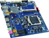
MDH11TI Quick Reference Guide 1 2 3 4 5 6 7 8 9 10 11 No. Code 1 MIC_IN Description Audio Mic In port Rear I/O Connector 2 LINE_OUT Audio Line Out port 34 3 4 12 5 6 SPKR HDMI CLR_CMOS DP Speaker cable connector HDMI port Clear CMOS jumper Display port connector 1 2 3 3 4 5 67 Speed LED Link/Activity LED 33 7 BATTERY 8 USB3_2 Battery cable connector USB 3.0 ports 9 USB3_1 USB 3.0 ports No. Desription 32 13 10 11 LAN DC_IN GbE LaN port DC In power connector 1 DC In power connector 2 GbE Eternet LAN port 10/100/1000 LAN LED: 31 12 ATX_19V 13 FUSB2_5 2 pin power connector USB 2.0 header 3 USB 3.0 ports 4 Display port connector State Description 30 16 15 14 14 SATAIII_2 SATAIII_1 SATAIII_0 SATA 6Gb/s connectors 5 HDMI port 6 Line Out port (Green) 7 Mic In port (Pink) Yellow On Green On 1Gbps data rate 100Mbps data rate 15 FUSB2_1 USB 2.0 header Off 10Mbps data rate 17 16 SYS_FAN 17 FUSB2_2 System fan connector USB 2.0 header 18 FUSB2_4 USB 2.0 headerr 18 19 SATA_PWR Hard disk power connector The HDMI connector is HDCP compliant and supports Dolby True HD and DTS HD 20 MON_SW Monitor power switch header Master Audio formats. It also supports up to 192KHz/24bit 8-channel LPCM audio 29 24 21 19 22 CPU_FAN SYS_PANEL CPU fan connector Front panel header 23 LVDS LVDS connector 24 SO_DIMM1 DDR3L SO-DIMM slot output. You can use this port to connect your HDMI-supported monitor. The maximum supported resolution is 4096x2160@24Hz or 2560x1600@60Hz, but the actual resolutions supported are dependent on the monitor being used. 20 25 26 FPD_PWR FPD LVDS power select jumper (12V/19V) Flat Panel Display connector 21 27 28 BL_SW LCD_VCC Back light brightness switch LVDS Drive voltage jumper 22 29 30 CPU TPM_LPC Intel 6th Generation Core Processor with LGA 1151 socket TPM module connector 31 M2_E 32 M2_M M.2 slot (PCIe Gen2 x1, Support NGFF-2230, E-Key) M.2 slot (SATA 6Gb/s) Power Connector/ 䕚๕ CPU/System FAN/ 䔎ࣂ 28 27 26 25 23 33 DMIC_CON Digital Mic connector 34 FP_AUDIO Front audio header 1 No. Pin Define 1 GND 2 19V 4 1 4 No. Pin Define 1 GND 2 +12V 3 Sense 2 1 4 Speed Control Back Light Switch Header 12 No. Pin Define 1 Back light down 2 Back light up Battery Cable Connector 2 1 No. Pin Define 1 RTC reset 2 GND Front Panel Header 12 No. Pin Define 1 HDD LED+ 2 Power LED+ 3 HDD LED- 4 Power LED- 9 10 5 GND 6 Power Button+ 7 Reset Button 8 Power Button- 9 GND 10 No Pin USB 2.0 Header 1 2 No. 1 2 3 4 9 10 5 6 7 8 9 10 Pin Define Power (5V) Power (5V) USB DXUSB DYUSB DX+ USB DY+ GND GND No Pin No Connect 1 No. Pin Define 1 VCC 2 USB3 USB+ 5 4 GND 5 No Pin TPM LPC Connector No. Pin Define 1 Clock 2 P_3V3_AUX 3 LPC_RST 2 1 14 13 4 5 6 P3V3 LPC_LAD0 IRQ_SERIAL 7 LPC_LAD1 8 TPM_DET(Default H) 9 LPC_LAD2 10 No Pin 11 LPC_LAD3 12 GND 13 LPC_FRAME_N 14 GND Installing CPU/ 安装 CPU Memory Population Configuration SATA Connector/SATA 接口 No. Pin Define 7 1 GND 1 2 TXP 3 TXN 4 GND 5 RXN 1 6 RXP 7 GND No. 40 1 2 3 4 5 6 7 8 9 10 Pin Define No. +RXO3_C 11 -RXO3_C 12 +RXO2_C 13 -RXO2_C 14 +RXO1_C 15 -RXO1_C 16 +RXO0_C 17 -RXO0_C 18 +RXE3_C 19 -RXE3_C 20 LVDS Pin Define No. +RXE2_C 21 -RXE2_C 22 +RXE1_C 23 -RXE1_C 24 +RXE0_C 25 -RXE0_C 26 GND 27 LCD_VCC 28 LCD_VCC 29 LCD_VCC 30 Pin Define No. No Connect 31 VCC3 32 GND 33 -Cable Detect 34 GND 35 +RXECLKO_C 36 -RXECLKO_C 37 GND 38 GND 39 GND 40 Pin Define SMB_CLK_CON SC_BKLT_EN SC_BKLT_CTRL +RXECLKE_C -RXECLKE_C FPD_19V FPD_19V FPD_19V No Connect SMB_DATA_CON Flat Panel Display Connector 8 1 No. Pin Define 1 Backlight enable 2 Backlight control 3 Backlight inverter power 4 Backlight inverter power 5 GND 6 GND 7 Panel brightness increase 8 Panel brightness decrease Speaker Cable Connector No. Pin Define 1 41 Speaker Out R- 2 Speaker Out R+ 3 Speaker Out L+ 4 Speaker Out L- Monitor Power Switch 1 No. 1 22 Pin Define High/ow: turn on/off monitor GND Digital MIC In Connector 1 No. Pin Define 1 VCC 2 DMI Data 5 Front Audio Connector 9 1 No. Pin Define 1 MIC2_L 2 GND 10 2 3 MC2_R 4 P3V3 5 LINE2_R No. Pin Define 6 MIC2_JD 7 F_Audio_Sense 8 No Pin 9 LINE2_L 10 LINE2_JD Jumper Settings 1 No. Desription 1 Clear CMOS Jumper Open: Normal operation (Default setting) Close: Clear CMOS data. 2 LVDS Power Select Jumper 1-2 Close: Set to 12V. 2-3 Close: Set to 19V. (Default setting) 3 LVDS Drive Voltage Jumper 1-2 Close: Set to 3V. 2-3 Close: Set to 5V. (Default setting) 32
-
 1
1
 |
 |