Gigabyte MDQ17AI Manual - Page 1
Gigabyte MDQ17AI Manual
 |
View all Gigabyte MDQ17AI manuals
Add to My Manuals
Save this manual to your list of manuals |
Page 1 highlights
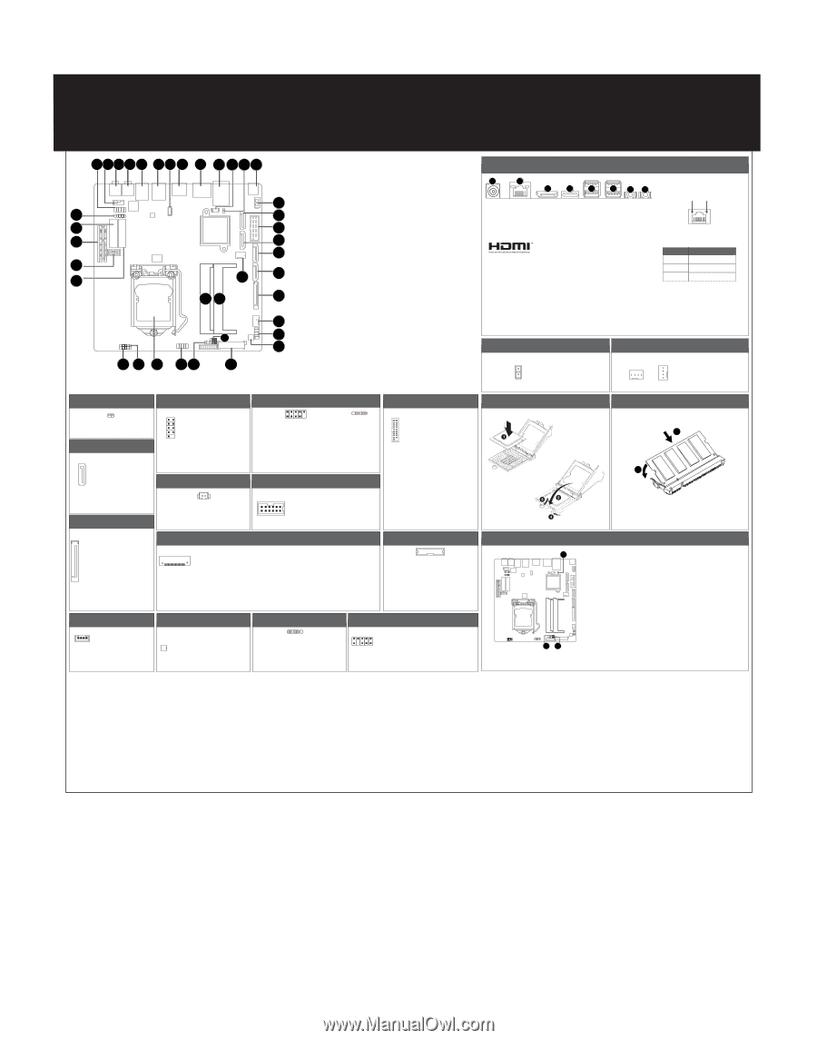
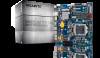
MDQ17AI Quick Reference Guide 1 2 3 4 5 6 7 8 9 10 11 12 13 14 38 15 37 16 36 17 18 35 34 24 19 26 25 20 21 27 22 23 33 32 31 30 29 28 No. Code 1 FP_AUDIO 2 SPKR 3 MIC_IN 4 LINE_OUT 5 USB3_2 6 USB3_1 7 NFC 8 HDMI 9 DP 10 LAN 11 BATTERY 12 CLR_CMOS 13 DC_IN 14 ATX_19V 15 SATAIII_3 16 FUSB3_1 17 SATAIII_2 18 SATAIII_1 19 SATAIII_0 20 SATA_PWR 21 CPU_FAN 22 SYS_PANEL 23 MON_SW 24 SYS_FAN 25 SODIMM2 26 SODIMM1 27 FPD_PWR LCD_VCC 28 LVDS 29 BL_SW 30 FUSB2_3 31 CPU 32 FUSB2_2 33 FUSB2_4 34 M2_E 35 COM1 36 PCIE4X 37 M2_M 38 DMIC_CON Description Front audio header Speaker cable connector Audio Mic In port Audio Line Out port USB 3.0 ports USB 3.0 ports NFC connector HDMI port Display port connector GbE LAN port Battery cable connector Clear CMOS jumper DC In power connector 2 pin power connector SATA 6Gb/s connector USB 3.0 header SATA 6Gb/s connector SATA 6Gb/s connector SATA 6Gb/s connector Hard disk power connector CPU fan connector Front panel header Monitor power switch header System fan connector DDR3L SO-DIMM slot#2 DDR3L SO-DIMM slot#1 LVDS power select jumper (12V/19V/top) LVDS Drive voltage jumper (bottom) LVDS connector Back light brightness switch USB 2.0 header Intel LGA1151 socket USB 2.0 header USB 2.0 header M.2 slot (PCIe Gen3 x1, Support NGFF-2230, E-Key) Serial port cable connector PCI Express x4 slot M.2 slot (PCIe Gen3 x4 or SATA 6Gb/s x1, Support NGFF-2260/2280, M-Key) Digital Mic connector Back Light Switch Header 12 No. Pin Define 1 Back light down 2 Back light up SATA Connector/SATA 接口 7 No. Pin Define 1 GND 2 TXP 3 TXN 4 GND 1 5 RXN 6 RXP 7 GND Hard disk power connectornnector Front Panel Header 12 No. Pin Define 1 HDD LED+ 2 Power LED+ 3 HDD LED- 4 Power LED- 9 10 5 GND 6 Power Button+ 7 Reset Button 8 Power Button- 9 GND 10 No Pin Battery Cable Connector 2 1 No. Pin Define 1 Battery+ 2 GND USB 2.0 Header 2 10 1 9 5 1 No. Pin Define No. Pin Define 1 Power (5V) 6 USB DY+ 2 Power (5V) 7 GND 3 USB DX- 8 GND 4 USB DY- 9 No Pin 5 USB DX+ 10 No Connect No. Pin Define 1 VCC 2 USB3 USB+ 4 GND 5 No Pin Serial Port Cable Connector No. Pin Define No. Pin Define 1 9 1 NDCD- 6 NCTS- 2 NDSR- 7 NDTR- 3 NRXD- 8 RI-/12V/5V 2 10 4 NRTS- 9 GNND 5 NTXD- 10 No Connect USB 3.0 Header 11 20 1 10 No. Pin Define 1 Power 2 IntA_P1_SSRX3 IntA_P1_SSRX+ 4 GND 5 IntA_P1_SSTX6 IntA_P1_SSTX+ 7 GND 8 IntA_P1_D9 IntA_P1_D+ 10 OC 11 IntA_P2_D+ 12 IntA_P2_D13 GND 14 IntA_P2_SSTX+ 15 IntA_P2_SSTX16 GND 17 IntA_P2_SSRX+ 18 IntA_P2_SSRX19 Power 20 No Pin N2 No. Pin Define No. Pin Define 1 VCC3 11 GND 2 VCC3 12 GND 3 VCC3 13 +12V 1 4 GND 14 +12V 5 GND 15 +12V 6 GND P1 GND 7 VCC P2 GND 8 VCC N1 GND 1 9 VCC N2 GND 10 GND No. 40 1 2 3 4 5 6 7 8 9 10 Pin Define No. +RXO3_C 11 -RXO3_C 12 +RXO2_C 13 -RXO2_C 14 +RXO1_C 15 -RXO1_C 16 +RXO0_C 17 -RXO0_C 18 +RXE3_C 19 -RXE3_C 20 LVDS Pin Define No. +RXE2_C 21 -RXE2_C 22 +RXE1_C 23 -RXE1_C 24 +RXE0_C 25 -RXE0_C 26 GND 27 LCD_VCC 28 LCD_VCC 29 LCD_VCC 30 Pin Define No. No Connect 31 VCC3 32 GND 33 -Cable Detect 34 GND 35 NC 36 -RXECLKO_C 37 GND 38 GND 39 GND 40 Pin Define SMB_CLK_CON SC_BKLT_EN SC_BKLT_CTRL +RXECLKE_C -RXECLKE_C FPD_19V FPD_19V FPD_19V No Connect SMB_DATA_CON Flat Panel Display Connector 8 1 No. Pin Define 1 Backlight enable 2 Backlight control 3 Backlight inverter power 4 Backlight inverter power 5 GND 6 GND 7 Panel brightness increase 8 Panel brightness decrease Speaker Cable Connector No. Pin Define 1 41 Speaker Out R- 2 Speaker Out R+ 3 Speaker Out L+ 4 Speaker Out L- Monitor Power Switch 1 No. 1 22 Pin Define High/ow: turn on/off monitor GND Digital MIC In Connector 1 5 No. Pin Define 1 VCC 2 DMI DATA 3 GND 4 DMIC CLK 5 No Pin Front Audio Connector 9 1 No. Pin Define No. Pin Define 1 MIC2_L 6 MIC2_JD 2 GND 7 GND 10 2 3 MIC2_R 8 No Pin 4 FP_AUDIO_DET 9 LINE2_L 5 LINE2_R 10 LINE2_JD Rear I/O Connector 1 2 3 4 5 5 67 No. Desription 1 DC In power connector 2 GbE Eternet LAN port 3 Display port connector 4 HDMI port No. Desription 5 USB 3.0 ports 6 Line Out port (Green) 7 Mic In port (Pink) The HDMI connector is HDCP compliant and supports Dolby True HD and DTS HD Master Audio formats. It also supports up to 192KHz/24bit 8-channel LPCM audio output. You can use this port to connect your HDMI-supported monitor. The maximum supported resolution is 4096x2160@24Hz or 2560x1600@60Hz, but the actual resolutions supported are dependent on the monitor being used. Speed LED Link/Activity LED 10/100/1000 LAN LED: State Yellow On Description 1Gbps data arte Green On 100Mbps data arte Off 10Mbps data arte Power Connector/ 䕚๕ 1 No. Pin Define 1 GND 2 19V 2 Installing CPU/ 安装 CPU CPU/System FAN/ 䔎ࣂ 4 No. Pin Define 1 GND 1 4 2 +12V 3 Sense 1 4 Speed Control Memory Population Configuration 1 2 Jumper Settings 1 No. Desription 1 Clear CMOS Jumper Open: Normal operation (Default setting) Close: Clear CMOS data. 2 LVDS Back Light Power Select Jumper 1-2 Close: Set to 12V. 2-3 Close: Set to 19V. (Default setting) 3 LVDS Logic/LCD Drive Voltage Jumper 1-2 Close: Set to 3V. 2-3 Close: Set to 5V. (Default setting) 32 PN Pin No. Definition
-
 1
1
 |
 |