Gigabyte MDQ17BI Manual - Page 1
Gigabyte MDQ17BI Manual
 |
View all Gigabyte MDQ17BI manuals
Add to My Manuals
Save this manual to your list of manuals |
Page 1 highlights
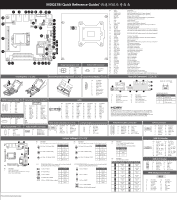
MDQ17BI Quick Reference Guide 12 39 38 37 36 35 34 3 4 5 8 9 10 11 12 6 13 7 41 14 42 15 16 40 17 18 20 19 21 22 23 25 24 27 26 28 33 32 31 30 29 Power Connector/ 䕚๕ No. Pin Define 3 11 GND 4 2 2 3 GND +12V 4 +12V Battery Cable Connector No. Pin Define 2 1 1 Battery+ 2 GND No. Code 1 AUDIO 2 USB30_LAN2 3 USB30_LAN1 4 BATTERY 5 HDMI_DP 6 EDP 7 LVDS 8 LSW 9 VGA_COM1 10 JCOM11 11 BATTERY 12 DC_IN2 13 JCOM12 14 JRS13/JRS14/ JRS12/JRS11 15 JRS21/JRS22/ JRS23/JRS24 16 COM2 17 JCOM21 18 SYS_FAN 19 GPIO_CN 20 JCOM22 21 TPM_LPC 22 MINI_PCIE 23 SATAIII_2 24 SATAIII_1 25 SATA_PWR1 26 SATA_PWR2 27 SATAIII_0 28 CLR_CMOS 29 SYS_PANEL 30 FSB20_2 31 FSB20_1 32 FSB30 33 CPU_FAN 34 SODIMM2 35 SODIMM1 36 CPU 37 PCIE16X 38 SPK_OUT 39 F_AUDIO 40 AT_CN 41 BKL_CN 42 M2_M Description Audio connectors GbE LAN port#2 (top)/USB 3.0 ports (buttom) GbE LAN port#1 (top)/USB 3.0 ports (buttom) Battery cable connector Display port connector (top)/HDMI 2.0 port (buttom) Embedded Display Port connector LVDS connector LVDS resolution jumper Serial port (top)/VGA port (buttom) 5V/12V/RI signal select jumper for Serial port header#1 Battery cable connector DC In power connector RS232/RS422/RS485 select jumper for Serial port header#1 RS232/RS422/RS485 select jumper for Serial port header#1 RS232/RS422/RS485 select jumper for Serial port header#2 Serial port header#2 5V/12V/RI signal select jumper for Serial port header#2 System fan connector GPIO connector RS232/RS422/RS485 select jumper for Serial port header#2 TPM module connector Mini PCI Express connector SATA 6Gb/s connector#2 SATA 6Gb/s connector#1 Hard disk power connector #1 Hard disk power connector #2 SATA 6Gb/s connector#0 Clear CMOS jumper Front panel header USB 2.0 header#2 USB 2.0 header#1 USB 3.0 header CPU fan connector DDR3L SO-DIMM slot#2 DDR3L SO-DIMM slot#1 Intel LGA1151 socket PCI Express x16 slot Audio Amplifie connector Front audio connector AT/ATX power mode select jumper Back light brightness control connector M.2 slot (PCIe Gen3 x4, Support NGFF-2242/2280, M-Key) Installing CPU/ 安装 CPU Memory Population Configuration System Panel Header Rear I/O Connector 2 1 No. Pin Define 10 9 1 HDD LED+ 2 Power LED+ 3 HDD LED- 4 Power LED- 5 GND 21 6 Power Button+ 7 Reset Button 8 Power Button- 9 No Connect 10 No Pin SATA Connector/SATA 接口 Embedded Display Port connector 71 17 No. Pin Define 1 GND 2 TXP 3 TXN 4 GND 5 RXN 6 RXP 7 GND Hard disk power connectornnector No. Pin Define 1 +12V 4 12 GND 3 GND 4 VCC 1 19 2 20 No. Pin Define No. Pin Define 1 GND 11 eDP_1+ 2 GND 12 eDPAUX- 3 eDP_0- 13 GND 4 eDP_3- 14 ePDAUX+ 5 eDP_0+ 15 eDP_2- 6 eDP_3+ 16 GND 7 GND 17 eDP_2+ 8 -eDPSW 18 eDP_HDP_C 9 eDP_1- 19 VCC_LVDS 10 GND 20 VCC3_LVDS NOTE! Please ensure pin 8 is connected to Ground. CPU/System FAN/ 䔎ࣂ Audio Amplifie connector 1 No. 1 2 3 44 Pin Define GND +12V Sense Speed Control No. Pin Define 4 11 Speaker Out L+ 2 Speaker Out L- 3 Speaker Out R- 4 Speaker Out R+ LVDS No. Pin Define No. Pin Define No. Pin Define No. Pin Define 1 VCC3 11 A1M_C 21 A5P_C 31 GND 1 39 2 3 VCC VCC3 12 A0M_C 22 A4P_C 32 GND 13 GND 23 A5M_C 33 CLK2P_C 4 VCC 14 GND 24 A4M_C 34 CLK1P_C 2 40 5 SPC0 15 A3P_C 25 GND 35 CLK2M_C 6 SPD0 16 A2P_C 26 GND 36 CLK1M_C 7 GND 17 A3M_C 27 A7P_C 37 GND 8 GND 18 A2M_C 28 A6P_C 38 GND 9 A1P_C 19 GND 29 A7M_C 39 +12V 10 A0P_C 20 GND 30 A6M_C 40 +12V Front Audio Connector 1 9 No. Pin Define No. Pin Define 1 MIC_L 6 GND 2 GND 7 FAUDIO_JD 2 10 3 MIC_R 8 No Connect 4 -ACZ_DET 9 HPOUT_L 5 HPOUT_R 10 GND Back light brightness control connector No. Pin Define 5 1 VCC_LVDS 2 PWM_OUT 3 EN_BKLT 1 4 GND 5 +12V_LVDS 2 6 6 8 Speed LED Link/Activity LED 1 4 9 10 3 5 7 7 10/100/1000 LAN LED: No. Desription 1 DC In power connector 2 Serial Port 3 VGA port 4 Display port connector 5 HDMI 2.0 port No. Desription 6 GbE Eternet LAN port 7 USB 3.0 port 8 Line In port (Blue) 9 Line Out port (Green) 10 Mic In port (Pink) State Amber On Green On Off Description 1Gbps data rate 100Mbps data rate 10Mbps data rate The HDMI connector is HDCP compliant and supports Dolby True HD and DTS HD Master Audio formats. It also supports up to 192KHz/24bit 8-channel LPCM audio output. You can use this port to connect your HDMI-supported monitor. The maximum supported resolution is 4096x2160@24Hz or 2560x1600@60Hz, but the actual resolutions supported are dependent on the monitor being used. Serial Port Cable Connector 9 10 12 No. Pin Define No. Pin Define 1 NRXD2_D- 6 GND 2 NDCD2_D- 7 NCTS23 NDTR2_D- 8 NRTS24 NTXD2_D- 9 No Connect 5 NDSR2- 10 RI2-/1_5V/12V GPIO Connector 1 11 No. Pin Define No. Pin Define 1 SOGPO1 7 SOGPO4 2 SOGPI1 8 SOGPI4 3 SOGPO2 9 SMB_CLK 2 12 4 SOGI2 10 SMB_DATA 5 SOGPO3 11 VCC 6 SOGPI3 12 GND Jumper Settings USB 3.0 Header 9 2 3 4 6 8 5 7 1 No. Desription 1 Clear CMOS Jumper Open: Normal operation (Default setting) Close: Clear CMOS data. JRS22 JRS23 JRS21 JRS24 JJRRSS1134 JRS12 JRS11 No. Desription 2 5V/12V/RI signal select jumper for Serial port header#1 65 1-2 Close: 5V (Power COM) 21 6 5 3-4 Close: RI (Stand COM) Pin No. Definition 1 VCC 2 RI1-/5V/12V 3 NRI1- 21 65 5-6 Close: 12V (power COM) 4 RI1-/5V/12V 5 +12V 21 6 RI1-/5V/12V No. Desription 5 5V/12V/RI signal select jumper for Serial port header#2 65 1-2 Close: 5V (Power COM) 21 6 5 3-4 Close: RI (Stand COM) Pin No. Definition 1 VCC 2 RI2-/5V/12V 3 NRI2- 21 65 5-6 Close: 12V (power COM) 4 RI2-/5V/12V 5 +12V 21 6 RI2-/5V/12V 3/4 RS232/RS422/RS485 select jumper for Serial port header#1 (JCOM12/JRS13/JRS14/JRS11/JRS12) 2 1 6 5 1-2 Close: RS232 2 1 6 5 3-4 Close: RS422 2 1 6 5 5-6 Close: RS485 1-2 Close: RS422/RS485 Pin No. 1 2 3 Definition RXD232 RXD1 RXD422 4 RXD1 2-3Close: RS232 (Default setting) 5 RXD485 6 RXD1 6/7 RS232/RS422/RS485 select jumper for Serial port header#1 (JRS21/JRS22/JRS23/JRS24/JCOM22) 65 1-2 Close: RS232 Pin No. Definition 21 1 RXD232 65 3-4 Close: RS422 21 2 RXD2 3 RXD422 65 4 RXD2 5-6 Close: RS485 21 1-2 Close: RS422/RS485 5 RXD485 6 RXD2 2-3Close: RS232 (Default setting) No. Desription 8 AT/ATX Power Mode Select Jumper 1-2 Close: AT mode. 2-3 Close: ATX mode. (Default setting) Pin No. Definition 1 TXD5 AT Mode 2 TXD5 3 TXD5 AT No. Desription 9 LVDS Resolution Jumper Jumper Setting Resolution 800x600 18bit Jumper Setting Resolution 1366x768 24bit 1024x768 18bit 1440x900 18bit 1024x768 24bit 1400x1050 24bit 1024x600 18bit 1600x900 24bit 1280x800 18bit 1280x960 18bit 1680x1050 24bit 1600x1200 24bit 1280x1024 24bit 1920x1080 24bit 1366x768 18bit 1920x1200 24bit No. Pin Define No. Pin Define 1 Power 11 IntA_P2_D+ 2 IntA_P1_SSRX- 12 IntA_P2_D- 3 IntA_P1_SSRX+ 13 GND 1 10 4 GND 14 IntA_P2_SSTX+ 20 11 5 IntA_P1_SSTX- 15 IntA_P2_SSTX- 6 IntA_P1_SSTX+ 16 GND 7 GND 17 IntA_P2_SSRX+ 8 IntA_P1_D- 18 IntA_P2_SSRX- 9 IntA_P1_D+ 19 Power 10 OC 20 No Pin USB 2.0 Header 10 9 No. Pin Define No. Pin Define 1 Power (5V) 6 USB DY+ 2 Power (5V) 7 GND 3 USB DX- 8 GND 4 USB DY- 9 No Pin 21 5 USB DX+ 10 No Connect TPM Module Connector 2 1 No. Pin Define 1 LPC_CLK0_B 2 3VDUAL 3 -PFMRST 4 VCC3 5 LPC_LAD0 6 IRQ_SERIAL 7 LPC_LAD1 14 13 No. Pin Define 8 TPM_DET_N 9 LPC_LAD2 10 NC 11 LPC_LAD3 12 GND 13 LFRAME# 14 GND PN:xxxxxxxxxxxxxxxxxxxxxx
-
 1
1
 |
 |