Gigabyte MW21-SE0 Manual
Gigabyte MW21-SE0 Manual
 |
View all Gigabyte MW21-SE0 manuals
Add to My Manuals
Save this manual to your list of manuals |
Gigabyte MW21-SE0 manual content summary:
- Gigabyte MW21-SE0 | Manual - Page 1
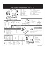
MW21-SE0/MW21-SE1 Quick Reference Guide 37 38 1 2 3 4 5 36 6 30 31 35 29 7 28 32 34 27 26 33 25 8 24 9 No. Code Description 1 USB_LAN1 LAN port #1 (top) / USB 3.0 ports (bottom) (MW21-SE1) USB_LAN1 USB 3.0 ports (bottom) (MW21-SE0 ATX Power/ 䕚๕ PMBUS 14 MW21-SE0 Supported - Gigabyte MW21-SE0 | Manual - Page 2
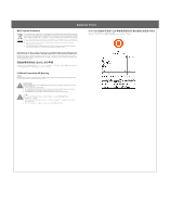
contact your local government office, your household waste disposal service or where you purchased the product for details of environmentally 's manual and we will be glad to help you with your effort. China RoHS Restriction of Hazardous Substances (RoHS) Directive Statement GIGABYTE products
-
 1
1 -
 2
2
 |
 |
1
2
3
4
5
6
7
8
9
11
10
12
13
14
15
16
17
18
19
20
22
21
23
24
25
26
27
28
29
30
35
31
32
33
37
38
34
36
HDD Back Plane Board Header/
硬盤背板排針
Front Panel Header/
前面板
1
24
23
2
1
2
9
10
No.
Pin Define
1
HDD LED+
2
Power LED+
3
HDD LED-
4
Power LED-
5
GND
6
Power Bu°on+
7
Reset Bu°on
8
Power Bu°on-
9
No Connect
10
No Pin
No.
Pin Define
1
Power LED+
3
No Pin
5
Power LED-
7
HDD LED+
9
HDD LED-
11
Power Bu°on
13
GND
15
Reset Bu°on+
17
GND
19
ID Switch+
21
ID Switch-
23
NMI Switch-
No.
Pin Define
2
5V Standby
4
ID LED+
6
ID LED-
8
System Front Board LED+
10
System Status LED-
12
LAN1 Ac±ve LED+
14
LAN1 Link LED-
16
SMBus Data
18
SMBus Clock
20
Case Open
22
LAN2 Ac±ve LED
24
LAN2 Link LED-
ATX Power/
电源
PMBUS
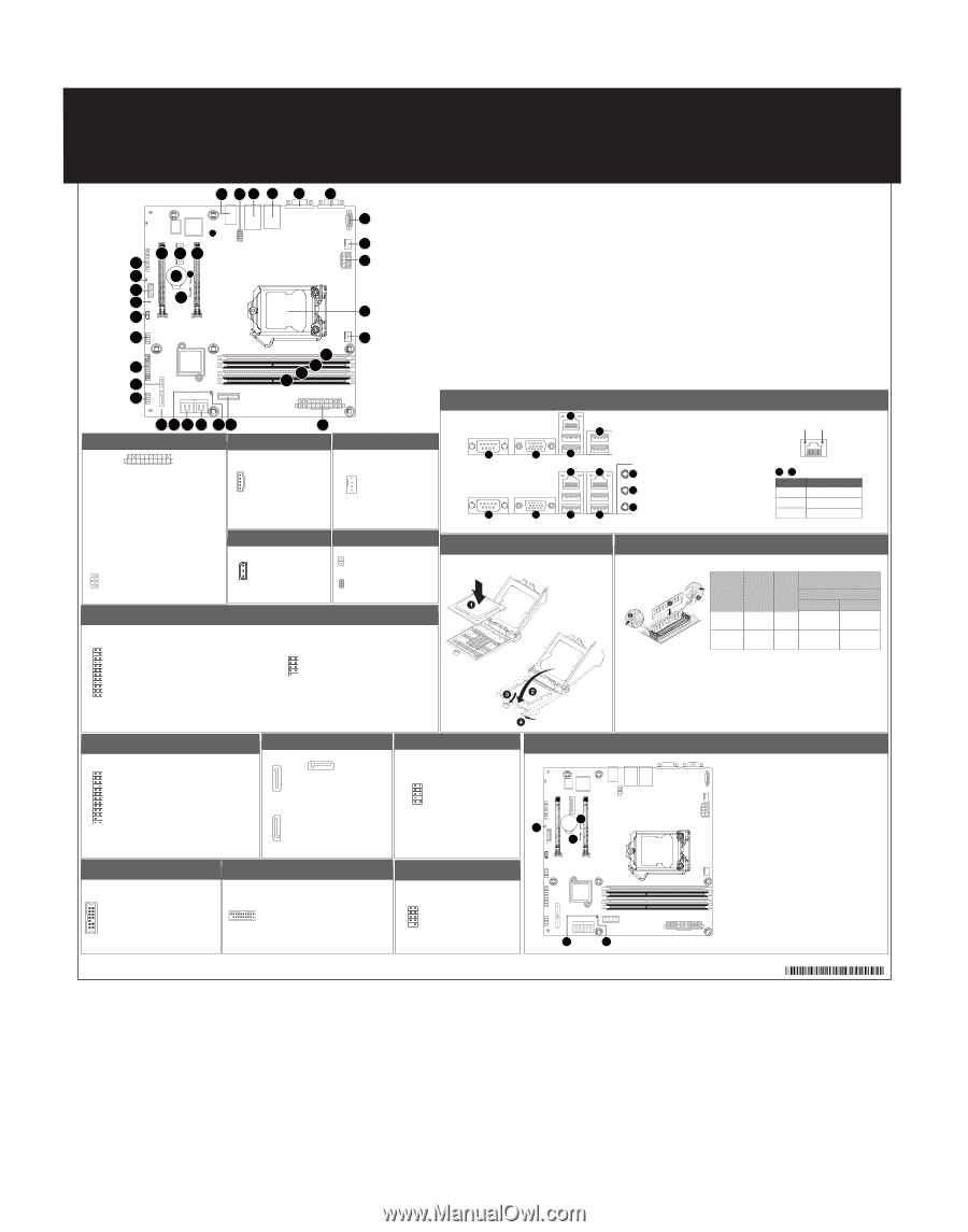
Installing CPU/
安装
CPU
Memory Popula°on Configura°on/
安装内存
Type
Ranks Per
DIMM and
Data Width
Speed (MT/s);
Slot Per Channel (SPC) and
DIMM Per Channel (DPC)
UDIMM
Unbuffered
DDR4 ECC
UDIMM
Unbuffered
DDR4 non-ECC
SR, DR
1.2V
1.2V
2133
2133
Supported
Voltage
DR
2133
2133
2 Slot Per Channel
1DPC
2DPC
Rear I/O Connector/
后面板接口
Off
State
Description
Yellow On
1Gbps data arte
Green On
100Mbps data arte
10Mbps data arte
SATA Connector/SATA
接口
1
7
7
1
7
1
No.
Pin Define
1
GND
2
TXP
3
TXN
4
GND
5
RXN
6
RXP
7
GND
TPM Connector/
可信平台模块
IPMB
1
3
No.
Pin Define
1
Clock
2
GND
3
Data
CPU/System FAN/
风扇
USB 2.0 Header
USB 3.0 Header
1
20
10
11
No.
Pin Define
1
Power
2
IntA_P1_SSRX-
3
IntA_P1_SSRX+
4
GND
5
IntA_P1_SSTX-
6
IntA_P1_SSTX+
7
GND
8
IntA_P1_D-
9
IntA_P1_D+
10
NC
No.
Pin Define
11
IntA_P2_D+
12
IntA_P2_D-
13
GND
14
IntA_P2_SSTX+
15
IntA_P2_SSTX-
16
GND
17
IntA_P2_SSRX+
18
IntA_P2_SSRX-
19
Power
20
No Pin
Front Audio Connector/
前置音频
Case Open Intrusion Header
Jumper Se±ngs/
跳线设置
1
2
3
4
5
No.
Desrip±on
1
Clear CMOS Jumper
Open: Normal opera±on (Default se²ng)
Close: Clear CMOS data.
2
ME Update Jumper
1-2 Close: Normal opera±on (Default se²ng)
2-3 Close: ME update.
3
S3 Power On Select Jumper (MW21-SE1 Only)
1-2 Close: Stop an ini±al power on when BMC is not ready.
2-3 Close: Keep ini±al power on. (Default se²ng)
4
Clearing Supervisor Password Jumper
1-2 Close: Normal opera±on. (Default se²ng)
2-3 Close: Skip supervisor password.
5
ME Recovery Jumper
1-2 Close: Normal opera±on. (Default se²ng)
2-3 Close: ME recovery mode.
4
2
2
3
3
4
4
4
4
6
7
8
5
5
1
1
MW21-SE0/MW21-SE1 Quick Reference Guide/
快速测试参考指南
1
4
1
5
1
5
4
8
1
2
13 14
1
2
2
1
10
9
25 26
No.
Pin Define
1
3.3V
2
3.3V
3
GND
4
+5V
5
GND
6
+5V
7
GND
8
Power Good
9
5VSB
10
+12V
11
+12V
12
3.3V
No.
Pin Define
1
GND
2
GND
3
GND
4
GND
No.
Pin Define
1
PMBus Clock
2
PMBus Data
3
PMBus Alert
4
GND
5
3.3V Sense
No.
Pin Define
1
GND
2
+12V
3
Sense
4
Speed Control
MW21-SE1
For MW21-SE1 Only
For MW21-SE1 Only
For MW21-SE1 Only
For MW21-SE1 Only
MW21-SE0
No.
Pin Define
1
Clock
2
P_3V3_AUX
3
LPC_RST
4
P3V3
5
LPC_LAD0
6
IRQ_SERIAL
7
LPC_LAD1
Open: Normal opera±on.
Closed: Ac±ve chassis intrus±on alert.
No.
Pin Define
1
MIC2_L
2
GND
3
MC2_R
4
P3V3
5
LINE2_R
6
MIC2_JD
7
F_Audio_Sense
8
No Pin
9
LINE2_L
10
LINE2_JD
No.
Pin Define
1
Power (5V)
2
Power (5V)
3
USB DX-
4
USB DY-
5
USB DX+
6
USB DY+
7
GND
8
GND
9
No Pin
10
No Connect
No.
Code
Descrip±on
1
USB_LAN1
LAN port #1 (top) / USB 3.0 ports (bo°om) (MW21-SE1)
USB_LAN1
USB 3.0 ports (bo°om) (MW21-SE0)
2
USB_LAN2
LAN port #2 (top) / USB 3.0 ports (bo°om)
3
VGA_1
VGA port
4
COM1
Serial port
5
PMBUS
PMBus connector (MW21-SE1 Only)
6
SYS_FAN1
System fan connector#1
7
P12V_AUX
8 pin power connector
8
CPU0
Intel LGA1151 Socket H4
9
CPU0_FAN
CPU fan connector
10
DIMM_P0_A0
Channel 1 slot 0
11
DIMM_P0_A1
Channel 1 slot 1
12
DIMM_P0_B0
Channel 2 slot 0
13
DIMM_P0_B1
Channel 2 slot 1
14
ATX1
24 pin main power connector
15
F_USB3
USB 3.0 header
16
ME_RCVR
ME recovry jumper
17
SATA_2_3
SATA 3 6Gb/s connectors
18
SATA_0_1
SATA 3 6Gb/s connectors
19
BIOS_PWD
Clearing Supervisor Password jumper
No.
Desrip±on
1
Serial port
2
VGA port
3
GbE Eternet LAN port
4
USB 3.0 port
5
KVM Server Management 10/100/1000
LAN Port (Dedicated LAN Port)
6
Line In Jack (Blue)
7
Line Out Jack (Green)
8
Mic In Jack (Pink)
All channels in system run at the fastest common frequency.
Mixing ECC and non-ECC UDIMMs anywhere on the pla³orm is not supported.
1 and 2 DPC is supported at 2133MHz.
所有通道模式以最快的频率速度运行。
此主板不支持ECC与非ECC内存模组混合使用。
1
与
2 DPC
均支持
2133MHz
速度
。
Speed LED
10/100/1000 LAN LED:
Link/Ac±vity
LED
1
13
12
24
No.
Code
Descrip±on
20
SATA_5
SATA 3 6Gb/s connector
21
FP_2
Front panel header (For PC System)
22
SATA_4
SATA 3 6Gb/s connector
23
FP_1
Front panel header (For Server System/MW21-SE1 Only)
24
F_USB2
USB 2.0 header
25
IPMB
IPMB connector
(MW21-SE1 Only)
26
CASE_OPEN
Case open intrusion alert header
27
TPM
TPM module connector
28
S
3_MASK
S3 Power On Select jumper (MW21-SE1 Only)
29
BP_1
HDD back plane board header (For Server System/MW21-SE1 Only)
30
PCIE_3
PCI Express x16 slot
31
PCIE_2
PCI Express x4 slot
32
BAT
Ba°ery socket
33
ME_UPDATE
ME update jumper
34
CLR_CMOS
Clear CMOS jumper
35
PCIE_1
PCI Express x16 slot
36
LED_BMC
BMC firmware readiness LED (MW21-SE1 Only)
37
HD_AUDIO
Audio connectors
(MW21-SE1 Only)
38
F_AUDIO
Front audio connector (MW21-SE1 Only)
No.
Pin Define
13
3.3V
14
-12V
15
GND
16
PS_ON
17
GND
18
GND
19
GND
20
-5V
21
+5V
22
+5V
23
+5V
24
GND
10
9
2
1
5
+12V
6
+12V
7
+12V
8
+12V
No.
Pin Define
8
No Connect
9
LPC_LAD2
10
No Pin
11
LPC_LAD3
12
GND
13
LPC_FRAME_N
14
GND
For Server System (MW21-SE1)
For PC System (MW21-SE0)
No.
Pin Define
1
BP_SGP_CLK
3
BP_SGP_GLD
5
BP_SGP_DOUT
7
Key Pin
9
GND
11
BP_LED_G_N
13
BP_SGP_DIN
15
GND
17
GND
19
P_3V3_AUX
21
P_3V3_AUX
23
GND
25
BP_PRESENSE
No.
Pin Define
2
No Connect
4
FAN_SGP_GLD
6
GND
8
Reset
10
BP_LED_A_N
12
GND
14
No Connect
16
SMB_BP_DATA
18
SMB_BP_CLK
20
BMC_ACK
22
BMC_REQ
24
Key Pin
26
GND
P/N:12QM1-MW21S0-00R