Gigabyte MW21-SE0 Manual - Page 1
Gigabyte MW21-SE0 Manual
 |
View all Gigabyte MW21-SE0 manuals
Add to My Manuals
Save this manual to your list of manuals |
Page 1 highlights
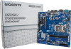
MW21-SE0/MW21-SE1 Quick Reference Guide 37 38 1 2 3 4 5 36 6 30 31 35 29 7 28 32 34 27 26 33 25 8 24 9 No. Code Description 1 USB_LAN1 LAN port #1 (top) / USB 3.0 ports (bottom) (MW21-SE1) USB_LAN1 USB 3.0 ports (bottom) (MW21-SE0) 2 USB_LAN2 LAN port #2 (top) / USB 3.0 ports (bottom) 3 VGA_1 VGA port 4 COM1 Serial port 5 PMBUS PMBus connector (MW21-SE1 Only) 6 SYS_FAN1 System fan connector#1 7 P12V_AUX 8 pin power connector 8 CPU0 Intel LGA1151 Socket H4 9 CPU0_FAN CPU fan connector 10 DIMM_P0_A0 Channel 1 slot 0 11 DIMM_P0_A1 Channel 1 slot 1 12 DIMM_P0_B0 Channel 2 slot 0 13 DIMM_P0_B1 Channel 2 slot 1 14 ATX1 24 pin main power connector 15 F_USB3 USB 3.0 header 16 ME_RCVR ME recovry jumper 17 SATA_2_3 SATA 3 6Gb/s connectors 18 SATA_0_1 SATA 3 6Gb/s connectors 19 BIOS_PWD Clearing Supervisor Password jumper No. Code Description 20 SATA_5 SATA 3 6Gb/s connector 21 FP_2 Front panel header (For PC System) 22 SATA_4 SATA 3 6Gb/s connector 23 FP_1 Front panel header (For Server System/MW21-SE1 Only) 24 F_USB2 USB 2.0 header 25 IPMB IPMB connector (MW21-SE1 Only) 26 CASE_OPEN Case open intrusion alert header 27 TPM TPM module connector 28 S3_MASK S3 Power On Select jumper (MW21-SE1 Only) 29 BP_1 HDD back plane board header (For Server System/MW21-SE1 Only) 30 PCIE_3 PCI Express x16 slot 31 PCIE_2 PCI Express x4 slot 32 BAT Battery socket 33 ME_UPDATE ME update jumper 34 CLR_CMOS Clear CMOS jumper 35 PCIE_1 PCI Express x16 slot 36 LED_BMC BMC firmware readiness LED (MW21-SE1 Only) 37 HD_AUDIO Audio connectors (MW21-SE1 Only) 38 F_AUDIO Front audio connector (MW21-SE1 Only) 10 23 11 12 22 13 21 Rear I/O Connector 20 19 18 17 16 15 ATX Power/ 䕚๕ PMBUS 14 MW21-SE0 CPU/System FAN/ 䔎ࣂ 3 4 1 13 No. Pin Define 1 3.3V 2 3.3V 3 GND 4 +5V 5 GND 6 +5V 7 GND 8 Power Good 9 5VSB 10 +12V 11 +12V 12 3.3V 12 24 No. Pin Define 13 3.3V 14 -12V 15 GND 16 PS_ON 17 GND 18 GND 19 GND 20 -5V 21 +5V 22 +5V 23 +5V 24 GND 51 No. Pin Define 5 +12V 1 GND 6 +12V 2 GND 7 +12V 84 3 4 GND GND 8 +12V For MW21-SE1 Only 5 No. Pin Define 1 PMBus Clock 2 PMBus Data 3 PMBus Alert 4 GND 1 5 3.3V Sense 1 No. Pin Define 1 GND 2 +12V 3 Sense 44 Speed Control 1 MW21-SE1 1 2 4 3 5 2 4 4 IPMB 1 For MW21-SE1 Only No. Pin Define 1 Clock 2 GND 33 Data Case Open Intrusion Header Open: Normal operation. Closed: Active chassis intrustion alert. Installing CPU/ 安装 CPU Front Panel Header For Server System (MW21-SE1) 12 23 24 No. Pin Define No. 1 Power LED+ 2 3 No Pin 4 5 Power LED- 6 7 HDD LED+ 8 9 HDD LED- 10 11 Power Button 12 13 GND 14 15 Reset Button+ 16 17 GND 18 19 ID Switch+ 20 21 ID Switch- 22 23 NMI Switch- 24 Pin Define 5V Standby ID LED+ ID LEDSystem Front Board LED+ System Status LEDLAN1 Active LED+ LAN1 Link LEDSMBus Data SMBus Clock Case Open LAN2 Active LED LAN2 Link LED- For PC System (MW21-SE0) No. 1 12 2 3 4 5 9 10 6 7 8 9 10 Pin Define HDD LED+ Power LED+ HDD LEDPower LEDGND Power Button+ Reset Button Power ButtonNo Connect No Pin No. 1 2 3 4 5 6 67 8 7 8 Desription Serial port VGA port GbE Eternet LAN port USB 3.0 port KVM Server Management 10/100/1000 LAN Port (Dedicated LAN Port) Line In Jack (Blue) Line Out Jack (Green) Mic In Jack (Pink) Speed LED Link/Activity LED 4 5 10/100/1000 LAN LED: State Description Yellow On 1Gbps data arte Green On Off 100Mbps data arte 10Mbps data arte Memory Population Configuration Type Ranks Per DIMM and Data Width Supported Voltage UDIMM Unbuffered DDR4 ECC UDIMM Unbuffered DDR4 non-ECC SR, DR DR 1.2V 1.2V Speed (MT/s); Slot Per Channel (SPC) and DIMM Per Channel (DPC) 2 Slot Per Channel 1DPC 2DPC 2133 2133 2133 2133 All channels in system run at the fastest common frequency. Mixing ECC and non-ECC UDIMMs anywhere on the platform is not supported. 1 and 2 DPC is supported at 2133MHz. ECC与非ECC 1 2 DPC ѩ˕ܵ2133MHz HDD Back Plane Board Header 1 2 No. 1 3 5 7 9 11 13 15 25 26 17 19 21 23 25 For MW21-SE1 Only Pin Define No. BP_SGP_CLK 2 BP_SGP_GLD 4 BP_SGP_DOUT 6 Key Pin 8 GND 10 BP_LED_G_N 12 BP_SGP_DIN 14 GND 16 GND 18 P_3V3_AUX 20 P_3V3_AUX 22 GND 24 BP_PRESENSE 26 Pin Define No Connect FAN_SGP_GLD GND Reset BP_LED_A_N GND No Connect SMB_BP_DATA SMB_BP_CLK BMC_ACK BMC_REQ Key Pin GND SATA Connector/SATA 接口 7 7 1 No. Pin Define 1 1 GND 2 TXP 1 3 TXN 4 GND 5 RXN 6 RXP 7 GND 7 Front Audio Connector For MW21-SE1 Only 12 No. Pin Define 1 MIC2_L 2 GND 3 MC2_R 9 10 4 P3V3 5 LINE2_R 6 MIC2_JD 7 F_Audio_Sense 8 No Pin 3 9 LINE2_L 10 LINE2_JD TPM Connector 1 2 No. Pin Define No. Pin Define 1 Clock 8 No Connect 2 P_3V3_AUX 9 LPC_LAD2 1 3 LPC_RST 10 No Pin 4 P3V3 11 LPC_LAD3 20 5 LPC_LAD0 12 GND 13 14 6 IRQ_SERIAL 13 LPC_FRAME_N 7 LPC_LAD1 14 GND USB 3.0 Header No. Pin Define 1 Power 2 IntA_P1_SSRX- 3 10 4 IntA_P1_SSRX+ GND 5 IntA_P1_SSTX- 11 6 IntA_P1_SSTX+ 7 GND 8 IntA_P1_D- 9 IntA_P1_D+ 10 NC No. Pin Define 11 IntA_P2_D+ 12 IntA_P2_D13 GND 14 IntA_P2_SSTX+ 15 IntA_P2_SSTX16 GND 17 IntA_P2_SSRX+ 18 IntA_P2_SSRX19 Power 20 No Pin USB 2.0 Header 12 9 10 No. Pin Define 1 Power (5V) 2 Power (5V) 3 USB DX4 USB DY5 USB DX+ 6 USB DY+ 7 GND 8 GND 9 No Pin 10 No Connect 1 2 4 5 Jumper Settings No. Desription 1 Clear CMOS Jumper Open: Normal operation (Default setting) Close: Clear CMOS data. 2 ME Update Jumper 1-2 Close: Normal operation (Default setting) 2-3 Close: ME update. 3 S3 Power On Select Jumper (MW21-SE1 Only) 1-2 Close: Stop an initial power on when BMC is not ready. 2-3 Close: Keep initial power on. (Default setting) 4 Clearing Supervisor Password Jumper 1-2 Close: Normal operation. (Default setting) 2-3 Close: Skip supervisor password. 5 ME Recovery Jumper 1-2 Close: Normal operation. (Default setting) 2-3 Close: ME recovery mode. P/N:12QM1-MW21S0-00R
-
 1
1 -
 2
2
 |
 |