Gigabyte MX31-BS0 Manual - Page 1
Gigabyte MX31-BS0 Manual
 |
View all Gigabyte MX31-BS0 manuals
Add to My Manuals
Save this manual to your list of manuals |
Page 1 highlights
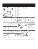
MX31-BS0 Quick Reference Guide 42 38 37 39 40 41 1 2 36 35 34 33 32 23 31 30 29 28 27 26 25 24 22 21 20 19 3 4 5 6 7 8 9 10 11 12 13 14 15 18 17 16 No. Code Description 1 USB3_LAN1 LAN port #1 (top) / USB 3.0 ports (bottom) 2 USB2_LAN2 LAN port #2 (top) / USB 2.0 ports (bottom) 3 VGA VGA port 4 COM1 Serial port 5 BUZZER Buzzer 6 SYS_FAN1 System fan connector# 7 PMBUS PMBus connector 8 P2 8 pin power connector (for CPU) 9 DIMM_P0_B1 Channel 2 slot 1 10 DIMM_P0_B0 Channel 2 slot 0 11 DIMM_P0_A1 Channel 1 slot 1 12 DIMM_P0_A0 Channel 1 slot 0 13 BIOS_RCVR BIOS recovery jumper 14 ME_RCVR ME recovry jumper 15 CASE_OPEN Case open intrusion alert header 16 SYS_FAN4 System fan connector#4 17 SYS_FAN3 System fan connector#3 18 P1 24 pin main power connector 19 SYS_FAN2 System fan connector#2 20 CPU0_FAN CPU fan connector 21 CPU0 Intel LGA1151 Socket H4 22 BAT Battery socket 23 CLR_CMOS Clear CMOS jumper 24 BIOS_PWD Clearing Supervisor Password jumper 25 SATA_0_1 SATA 3 6Gb/s connectors 26 SATA_2_3 SATA 3 6Gb/s connectors No. Code Description 27 SATA_DOM4 SATA port 4 DOM power connector 28 SATA4/SATA5 SATA 3 6Gb/s connectors (Supports SATA DOM) header 29 SATA_DOM5 SATA port 5 DOM power connector 30 USB_A1 Type A USB 2.0 connector 31 F_USB3 USB 3.0 header 32 F_USB2 USB 2.0 header 33 FP_1 Front panel header 34 IPMB IPMB connector 35 M2_MKEY M.2 slot (Dimension: 2280) No. Code Description 36 TPM TPM module connector 37 BP_1 HDD back plane board header 38 COM2 Serial port cable connector 39 PCIE_1 PCI Express x8 slot 40 PCIE_2 PCI Express x16 slot 41 ME_UPDATE ME update jumper 42 S3_MASK S3 Power On Select jumper 24 12 No. Pin Define No. 1 3.3V 13 2 3.3V 14 3 GND 15 4 +5V 16 5 GND 17 6 +5V 18 7 GND 19 8 Power Good 20 9 5VSB 21 10 +12V 22 11 +12V 23 12 3.3V 24 ATX Power/ 䕚๕ 13 1 Pin Define 3.3V -12V GND PS_ON GND GND GND -5V +5V +5V +5V GND 8 5 4 1 No. Pin Define 1 GND 2 GND 3 GND 4 GND 5 +12V 6 +12V 7 +12V 8 +12V CPU/System FAN/ 䔎ࣂ 4 1 1 No. Pin Define 1 GND 2 +12V 4 3 Sense 4 Speed Control 4 1 PMBUS 5 No. Pin Define 1 PMBus Clock 2 PMBus Data 3 PMBus Alert 4 1 5 GND 3.3V Sense IPMB 3 No. Pin Define 1 Clock 2 GND 3 Data 1 Front Panel Header 12 No. 1 3 5 7 9 11 13 15 23 24 17 19 21 23 Pin Define No. Power LED+ 2 No Pin 4 Power LED- 6 HDD LED+ 8 HDD LED- 10 Power Button 12 GND 14 Reset Button 16 GND 18 ID Button 20 GND 22 NMI Switch 24 Pin Define 5V Standby ID LED+ ID LEDStatus LED Green Status LED Amber LAN1 Active LED+ LAN1 Link LEDSMBus Data SMBus Clock Case Open LAN2 Active LED+ LAN2 Link LED- HDD Back Plane Board Header No. 12 1 3 5 7 9 11 13 15 17 25 26 19 21 23 25 Pin Define No. BP_SGCLK 2 BP_SGLOAD 4 BP_SGDOUT 6 Key Pin 8 GND 10 BP_LED_G_N 12 BP_SGDIN 14 GND 16 GND 18 P_3V3_AUX 20 P_3V3_AUX 22 GND 24 BP_PRESENSE 26 Pin Define No Connect FAN_SGP_Gate GND Reset BP_LED_A_N GND NC SMB_BP_DATA SMB_BP_CLK No Connect No Connect Key Pin GND SATA Connector/SATA 接口 1 No. Pin Define 1 GND 2 TXP 3 TXN 4 GND 5 RXN 7 6 RXP 7 GND SATA SGPIO Header/ ЕБ GPIO No. Pin Define 12 1 No Connect 2 No Pin 3 Data Out 4 GND 78 5 GND 6 Load 7 No Connect 8 Clock SATA DOM Support Power Header No. Pin Define 1 5V for SATA DOM 1 2 GND 3 No Connect Installing CPU/ 安装 CPU USB 3.0 Header 10 11 1 20 No. Pin Define 1 Power 2 IntA_P1_SSRX3 IntA_P1_SSRX+ 4 GND 5 IntA_P1_SSTX6 IntA_P1_SSTX+ 7 GND 8 IntA_P1_D9 IntA_P1_D+ 10 NC No. Pin Define 11 IntA_P2_D+ 12 IntA_P2_D13 GND 14 IntA_P2_SSTX+ 15 IntA_P2_SSTX16 GND 17 IntA_P2_SSRX+ 18 IntA_P2_SSRX19 Power 20 No Pin TPM Connector 1 2 No. 1 2 3 4 5 13 14 6 7 Pin Define Clock P_3V3_AUX LPC_RST P3V3 LPC_LAD0 IRQ_SERIAL LPC_LAD1 No. Pin Define 8 No Connect 9 LPC_LAD2 10 No Pin 11 LPC_LAD3 12 GND 13 LPC_FRAME_N 14 GND USB 2.0 Header 12 9 10 No. Pin Define 1 Power (5V) 2 Power (5V) 3 USB DX4 USB DY5 USB DX+ No. Pin Define 6 USB DY+ 7 GND 8 GND 9 No Pin 10 No Connect COM2 Connector 12 9 10 No. Pin Define No. Pin Define 1 NDCD- 6 NDSR- 2 NSIN 7 NRTS- 3 NSOUT 8 NCTS- 4 NDTR- 9 NRI- 5 GND 10 No Pin Case Open Intrusion Header Open: Normal operation. Closed: Active chassis intrustion alert. Rear I/O Connector 3 4 1 2 5 6 Speed LED Link/Activity LED 3 4 10/100/1000 LAN LED: State Yellow On Description 1Gbps data rate Green On Off 100Mbps data rate 10Mbps data rate No. Desription 1 Serial port 2 VGA port 3 GbE Eternet LAN port No. Desription 4 KVM Server Management 10/100/1000 LAN port (Shared LAN port) 5 USB 2.0 ports 6 USB 3.0 ports 6 5 1 2 Memory Population Configuration Type Ranks Per DIMM and Data Width Supported Voltage UDIMM Unbuffered SR DDR4 ECC UDIMM Unbuffered DR DDR4 non-ECC 1.2V 1.2V Speed (MT/s); Slot Per Channel (SPC) and DIMM Per Channel (DPC) 2 Slot Per Channel 1DPC 2DPC 2133 2133 2133 2133 All channels in system run at the fastest common frequency. Mixing ECC and non-ECC UDIMMs anywhere on the platform is not supported. 1 and 2 DPC is supported at 2133MHz. ECC与非ECC 1 2 DPC ѩ˕ܵ2133MHz Jumper Settings No. Desription 1 Clear CMOS Jumper 1-2 Close: Normal operation (Default setting) 2-3 Close: Clear CMOS data. 2 Clearing Supervisor Password Jumper 1-2 Close: Normal operation. (Default setting) 2-3 Close: Skip supervisor password. 3 BIOS Recovery Jumper 1-2 Close: Normal operation. (Default setting) 2-3 Close: BIOS recovery mode. 4 4 35 ME Recovery Jumper 1-2 Close: Normal operation. (Default setting) 2-3 Close: ME recovery mode. ME Update Jumper 1-2 Close: Normal operation (Default setting) 2-3 Close: ME update mode. 6 S3 Power On Select Jumper 1-2 Close: Stop an initial power on when BMC is not ready. 2-3 Close: Keep initial power on. (Default setting)
-
 1
1
 |
 |