Gigabyte R18N-F2A Manual - Page 1
Gigabyte R18N-F2A Manual
 |
View all Gigabyte R18N-F2A manuals
Add to My Manuals
Save this manual to your list of manuals |
Page 1 highlights
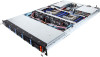
R18N-F2A Quick Installation Guide P/N: 1 2 34 5 6 65 66 64 7 67 9 62 63 53 54 61 60 59 58 57 11 10 12 14 13 8 15 52 55 56 51 50 48 46 44 43 41 39 37 35 33 31 30 49 47 45 42 40 38 36 34 32 16 28 26 24 29 27 25 No. 1 2 3 4 5 6 7 8 9 10 11 12 13 14 15 16 17 17 18 19 18 20 19 21 20 22 21 23 24 22 25 23 26 27 28 29 30 31 32 33 34 35 36 Motherboard Components Code Description No. USB3_MLAN BMC Management LAN port (top) / USB 3.0 ports (bottom) 37 COM1_USB2 RJ45 COM port (top) / USB 2.0 ports (bottom) 38 SW_ID ID switch button w/LED 39 LAN1 LAN port #1 40 LAN2 LAN port #2 41 VGA VGA port 42 RISER_SLOT3 PCI Express x16 slot 43 RISER_SLOT2 PCI Express x16 slot 44 PCIE_4 PCI Express x16 slot (mezzanine type) 45 BAT Battery socket 46 S3_MASK S3 Power On Select jumper 47 1-2 Close: Stop an initial power on when BMC is not ready. 48 2-3 Close: Keep initial power on. (Default setting) 49 CASE_OPEN Case open intrusion alert header 50 SW_RAID Intel/LSI Software RAID Key jumper 51 CLR_CMOS Clear CMOS jumper 52 1-2 Close: Normal operation (Default setting) 53 2-3 Close: Clear CMOS data. 54 PSU2 Hot-plug PSU module connector#2 55 PSU1 Hot-plug PSU module connector#1 ATX1 14 pin main power connector 12V_GPU3_2 4 pin 12V power connector 56 12V_GPU3_1 8 pin power connector 12V_GPU2_2 4 pin 12V power connector 12V_GPU2_1 8 pin power connector 57 12V_GPU1_2 4 pin 12V power connector 58 12V_GPU1_1 8 pin power connector 59 DIMM_P1_E0 Channel 1 slot 0 (for secondary CPU) 60 DIMM_P1_E1 Channel 1 slot 1 (for secondary CPU) 61 DIMM_P1_E2 Channel 1 slot 2 (for secondary CPU) DIMM_P1_F0 Channel 2 slot 0 (for secondary CPU) DIMM_P1_F1 Channel 2 slot 1 (for secondary CPU) 62 DIMM_P1_F2 Channel 2 slot 2 (for secondary CPU) CPU1 Intel LGA2011 Socket R3 (Secondary CPU) DIMM_P1_H2 Channel 3 slot 2 (for secondary CPU) 63 DIMM_P1_H1 Channel 3 slot 1 (for secondary CPU) 64 DIMM_P1_H0 Channel 3 slot 0 (for secondary CPU) 65 DIMM_P1_G2 Channel 4 slot 2 (for secondary CPU) 66 DIMM_P1_G1 Channel 4 slot 1 (for secondary CPU) DIMM_P1_G0 Channel 4 slot 0 (for secondary CPU) 67 Code DIMM_P0_A0 DIMM_P0_A1 DIMM_P0_A2 DIMM_P0_B0 DIMM_P0_B1 DIMM_P0_B2 CPU0 DIMM_P0_D2 DIMM_P0_D1 DIMM_P0_D0 DIMM_P0_C2 DIMM_P0_C1 DIMM_P0_C0 FP_1 BP_1 IPMB F_USB3 BUZZER1 PCH_ME ME_UPDATE MINI_CN1 MINI_CN2 SATA5 SATA4 BIOS_PWD BIOS_RCVR RISER_1_2 LED_BMC RISER_1_1 BMC_FRB TPM Description Channel 4 slot 0 (for primary CPU) Channel 1 slot 1 (for primary CPU) Channel 1 slot 2 (for primary CPU) Channel 2 slot 0 (for primary CPU) Channel 2 slot 1 (for primary CPU) Channel 2 slot 2 (for primary CPU) Intel LGA2011 Socket R3 (Primary CPU) Channel 4 slot 2 (for primary CPU) Channel 4 slot 1 (for primary CPU) Channel 4 slot 0 (for primary CPU) Channel 3 slot 2 (for primary CPU) Channel 3 slot 1 (for primary CPU) Channel 3 slot 0 (for primary CPU) Front panel header HDD back plane board header IPMB connector USB 3.0 header Buzzer ME recovery jumper 1-2 Close: Normal operation. (Default setting) 2-3 Close: ME recovery mode. ME update jumper 1-2 Close: Normal operation (Default setting) 2-3 Close: ME update mode. Mini-SAS cable connector#1 supports SATA3 6Gb/s Mini-SAS cable connector#2 supports SATA3 6Gb/s SATA3 6Gb/s connector SATA3 6Gb/s connector Clearing Supervisor Password jumper 1-2 Close: Normal operation. (Default setting) 2-3 Close: Skip supervisor password. BIOS recovery jumper 1-2 Close: Normal operation. (Default setting) 2-3 Close: BIOS recovery mode. PCI Express x16 slot (extension slot) BMC frmware readiness LED PCI Express x4 slot (extension slot) Force to Stop FRB Timer jumper 1-2 Close: Normal operation. (Default setting) 2-3 Close: Force to Stop FRB Timer. TPM module connector No. 24 23 1 3 5 7 9 11 13 15 17 2 1 19 21 23 Front Panel Header Pin Define No. Power LED+ 2 No Pin 4 Power LED- 6 HDD LED+ 8 HDD LED- 10 Power Button 12 GND 14 Reset Button+ 16 GND 18 ID Switch+ 20 ID Switch- 22 NMI Switch- 24 Pin Define 5V Standby ID LED+ ID LEDSystem Front Board LED+ System Status LEDLAN1 Active LED+ LAN1 Link LEDSMBus Data SMBus Clock Case Open LAN2 Active LED LAN2 Link LED- 12 25 26 HDD Back Plane Board Header No. Pin Define No. Pin Define 1 BP_SGP_CLK 2 No Connect 3 BP_SGP_GLD 4 FAN_SGP_GLD 5 BP_SGP_DOUT 6 GND 7 Key Pin 8 Reset 9 GND 10 BP_LED_A_N 11 BP_LED_G_N 12 GND 13 BP_SGP_DIN 14 No Connect 15 GND 16 SMB_BP_DATA 17 GND 18 SMB_BP_CLK 19 P_3V3_AUX 20 BMC_ACK 21 P_3V3_AUX 22 BMC_REQ 23 GND 24 Key Pin 25 BP_PRESENSE 26 GND System Cover System Components 2 3 4 1 1 1 3 No 1 2 3 4 5 6 7 8 9 CAUTION! Before you remove or install the system cover: Make sure the system is not turned on or connected to AC power. 注意! 12 10 11 13 2 3 4 10 56 78 9 11 10 1 Description No HDD bays 10 System fan #13 (FAN13) 11 System fan #11/#12 (FAN11/FAN12) 12 System fan #9/#10 (FAN9/FAN10) 13 System fan #7 (FAN7) System fan #5 (FAN5) System fan #3/#4 (FAN3/FAN4) System fan #1/#2 (FAN1/FAN2) System fan #15 (FAN15) Description Memory slots CPU heat sink PCIe riser bracket Power supply cage CAUTION! To connect system fan connector, follow the instruction: Blue/Red cable connect to odd numbered connector. White/Amber cable connect to even numbered connector. Fan Duct Installing CPU Heat Sink 1 3 2 Memory Population Configuration Type RDIMM RDIMM RDIMM RDIMM LRDIMM Ranks Per DIMM and Data Width Speed (MT/s); Slot Per Channel (SPC) and DIMM Per Channel (DPC) 1 Slot Per Channel 2 Slot Per Channel 1DPC 1DPC 2DPC SRx4 SRx8 2133 2133 2133 2133 1866 1866 DRx8 DRx4 2133 2133 2133 2133 1866 1866 QRx4 2133 2133 2133 When only one DIMM is used, it must be populated in memory slot0 first. Memory populated sequence must be followed with slot0/slot1/slot2 System will not boot normally with incorrect populated sequence. DIMM 0 0/插槽1/插槽2 System Fan 1 2 CAUTION! Before you remove or install the system fan: Make sure the system is not turned on or connected to the AC power. Disconnect all necessary cable connections. Failure to observe these warnings could result in personal injury or damage to the equipment Hard Disk Drive and Back Plane Board Front & Rear 3 4 2 4 1 SGPIO Decode Mode HDD Backplane Board Components 13 14 10 15 16 9 No Description 1 HDD#0 2 HDD#1 3 HDD#2 4 HDD#3 5 HDD#4 6 HDD#5 7 HDD#6 8 HDD#7 9 HDD#8 10 HDD#9 17 18 19 20 21 22 7 5 8 6 No Description No 11 SGPIO Port B 21 12 SGPIO Port A 22 13 Fan connector#16 23 14 Fan connector#15 24 15 Fan connector#2 25 16 Fan connector#1 26 17 Fan connector#4 27 18 Fan connector#3 28 19 Fan connector#6 29 20 Fan connector#5 30 31 23 24 25 26 27 28 System Front View 29 3 11 1 12 30 11 31 1 3 5 7 4 2 2 4 6 8 Description 12 Fan connector#8 Fan connector#7 No Description Fan connector#10 1 HDD bay#0 Fan connector#9 2 HDD bay#1 Fan connector#12 3 HDD bay#2 Fan connector#11 4 HDD bay#3 Fan connector#14 5 HDD bay#4 Fan connector#13 6 HDD bay#5 JP_SEL1 7 HDD bay#6 JP_SEL2 8 HDD bay#7 JP_SEL3 9 HDD bay#8 (Support NVMe) HDD Back Plane Board CPLD Configuration 10 HDD bay#9 (Support NVMe) 11 Front panle LEDs and buttons Normal Mode Shift Mode 12 USB 3.0 ports System Rear View 10 67 9 12 12 3 10 4 5 89 No Description 1 Power supply fan 2 Power supply module cord socket 3 VGA port 4 RJ-45 LAN ports 5 ID switch button w/LED 6 RJ-45 COM port 7 10/100/1000 Server management LAN port 8 USB 2.0 ports 9 USB 3.0 ports 10 Low-profle riser card bay 10/100/1000 LAN LED: SGPIO Port Host Interface HDD Configuration Port A SATA/SAS#0~#3 HDD#0~#3 Port B SATA/SAS#0~#3 HDD#4~#7 N/A SATA/SAS#0~#3 NVMe#0~#1 HDD#8~#9 Port A SATA/SAS#2~#5 HDD#0~#3 Port B SATA/SAS#0~#3 HDD#4~#7 N/A SATA/SAS#0~#1 NVMe#0~#1 HDD#8~#9 Speed LED Link/Activity LED State Yellow On Green On Description 1Gbps data arte 100Mbps data arte JP_SEL1 2-3 Close 1-2 Close Off 10Mbps data arte Jumper JP_SEL2 2-3 Close 2-3 Close JP_SEL3 2-3 Close 2-3 Close 1 2 3 PCI Express Card 1 2 3 Power Supply 1 2 6 4 5 6 4 5 4 3 CAUTION! Before you remove or install the power supplies: Make sure the system is not turned on or connected to AC power. 注意! 1 2 3 5 4 6 Front Panel LED and Buttons No. Name 1 Reset Button 2 ID Button 3 Power LED Color Status Green Green Solid On Blink N/A Off 4 HDD Status LED Green On Blink Amber On Green/Amber Blink N/A Off 5/6 LAN1/2 Active/Link LEDs Green Green Solid On Blink N/A Off Description Press the button to reset the system. Press the button to activate system identifcation. System is powered on. System is in ACPI S1 state (sleep mode). System is not powered on or in ACPI S5 state (power off). System is in ACPI S4 state (hibernate mode). HDD locate HDD access HDD access HDD fault No HDD access or no HDD fault. Link between system and network or no access. Data transmission or receiving is occurring. No data transmission or receiving is occurring. 编号 1 2 3 ID LED 4 LED 5/6 LAN1/LAN2活动LED 颜色 状态 ACPI S1 ACPIS5 ACPI S4
-
 1
1 -
 2
2
 |
 |
