Gigabyte WRX80-SU8-IPMI Quick guide - Page 2
Jumpers, Connectors, and LEDs - manual
 |
View all Gigabyte WRX80-SU8-IPMI manuals
Add to My Manuals
Save this manual to your list of manuals |
Page 2 highlights
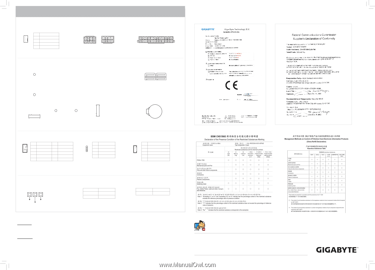
Jumpers, Connectors, and LEDs 18) CPU_FAN1 19) SYS_FAN1~6 ATX_CPU Pin Definition 1 GND 2 P12V 1 3 FAN_TACH 4 FAN_PWM 20/21) ATX_CPU/ATX_PCIE AT(2Xx4_, 1C2VPPUoweAr TCoXn_nePctCorsIE) 8 5 1 4 4 1 ATX_CPU 5 8 ATX_PCIE 22) ATX (2x12 Main Power Connector) ATX_PCIE 1 12 13 24 23/24) P_X4_M2_A/P_X4_M2_B (M.2 Socket 3 Connectors) 80 25/26) SATA_0_1/SATAG._Q2B_OF3M G.QBOFM (SATA 6Gb/s Connectors) SATA3 SATA2 SATA1 SATA0 40 80 40 P_X4_M2_B DEBUG PORT DEBUG PORT P_X4_M2_A 28) F_AUDIO Pin Definition 10 9 1 MIC2_L Pin Definition 2 GND 2 1 3 MIC2_R 5 LINE2_R 4 NC 6 Sense 7 FAUDIO_JD 8 No Pin 9 LINE2_L 10 Sense 29) SPEAKER 1 Pin Definition 1 5V 2 NA 3 NA 4 SPK- 27) BAT 30) TBT (Thunderbolt™ Pin Header) 1 Pin Definition 1 FORCE_POWER 2 SCI_EVENT 3 SLP_S3 4 SLP_S4 5 GND 31) PWR_SW (Power Button) 32) RST_SW (Reset Button) 33) QF_SW (Q-Flash Plus Button) PWR_SW QF_SW RST_SW 34) F_LED1 (Onboard Power LED) State Solid Red Solid Green Description Standby Power On 35) BMC_LED1 (BMC Heartbeat LED) State Description Blinking Green BMC Normal Copyright © 2020 GIGA-BYTE TECHNOLOGY CO., LTD. All rights reserved. The trademarks mentioned in this manual are legally registered to their respective owners. Disclaimer Information in this manual is protected by copyright laws and is the property of GIGABYTE. Changes to the specifications and features in this manual may be made by GIGABYTE without prior notice. No part of this manual may be reproduced, copied, translated, transmitted, or published in any form or by any means without GIGABYTE's prior written permission. For product-related information, check on our website at: https://www.gigabyte.com Contact Us GIGA-BYTE TECHNOLOGY CO., LTD. Address: No.6, Baoqiang Rd., Xindian Dist., New Taipei City 231, Taiwan TEL: +886-2-8912-4000, FAX: +886-2-8912-4005 Tech. and Non-Tech. Support (Sales/Marketing) : https://esupport.gigabyte.com WEB address (English): https://www.gigabyte.com WEB address (Chinese): https://www.gigabyte.com/tw
-
 1
1 -
 2
2
 |
 |