Gigabyte X299 AORUS Ultra Gaming Users Manual - Page 34
LED_C1/LED_C2 RGB RGBW LED Strip Extension Cable Headers
 |
View all Gigabyte X299 AORUS Ultra Gaming manuals
Add to My Manuals
Save this manual to your list of manuals |
Page 34 highlights
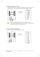
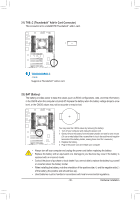
B_ S _S _ _ _B _ B_ S _S _ 13) LED_C1/LED_C2 (RGB (RGBW) LED Strip Extension Cable Headers) The headers can be used to connect a standard 5050 RGB (RGBW) LED strip (12V/G/R/B/W), with maximum power rating of 2A (12V) and maximum length of 2m. _ 1 LED_C1 _ 1 LED_C2 Pin No. 1 2 3 4 5 Definition 12V G R B W Connect one end of the RGB (RGBW) LED strip extension cable to the header and the other end to your RGB (RGBW) LED strip. The black wire (marked with a triangle on the plug) of the extension cable must be connected to Pin 1 (12V) of this header. The 12V pin (marked with an arrow) on the other end of the extension cable must be lined RGBW LED RGB LED upBw_ ith the 12V of the LEFD_UsStBr3ip. Be careful with the connection Strip Strip orientation of the LED strip; incorrect connection may lead to the B_ 1 12V USB 0_ B damage of the LED strip. If you are connecting a RGBW LED strip (5-pin), combine the two plFu_gUsSBo3f the extension cable together first. If yBo_u are connecting a RGB LED strip (4-pin), use only the 4-pin B_ USB 0_ B plug of the extension cable. For how to turn on/off the lights of the LED strip, refer to the instructions on in Chapter 2, "BIOS Setup," "Peripherals," or Chapter 5, "Unique Features," "APP Center\RGB Fusion." Before installing the devices, be sure to turn off the devices and your computer. Unplug the power cord from the power outlet to prevent damage to the devices. Hardware Installation - 34 -
-
 1
1 -
2
-
3
-
4
-
5
-
6
-
7
-
8
-
9
-
10
-
11
-
12
-
13
-
14
-
15
-
16
-
17
-
18
-
19
-
20
-
21
-
22
-
23
-
24
-
25
-
26
-
27
-
28
-
 29
29 -
 30
30 -
 31
31 -
 32
32 -
 33
33 -
 34
34 -
 35
35 -
 36
36 -
 37
37 -
 38
38 -
 39
39 -
40
-
41
-
42
-
43
-
44
-
45
-
46
-
47
-
48
-
49
-
50
-
51
-
52
-
53
-
54
-
55
-
56
-
57
-
58
-
59
-
60
-
61
-
62
-
63
-
64
-
65
-
66
-
67
-
68
-
69
-
70
-
71
-
72
-
73
-
74
-
75
-
76
-
77
-
78
-
79
-
80
-
81
-
82
-
83
-
84
-
85
-
86
-
87
-
88
-
89
-
90
-
91
-
92
-
93
-
94
-
95
-
96
-
97
-
98
-
99
-
100
-
101
-
102
-
103
-
104
-
105
-
106
-
107
-
108
-
109
-
110
-
111
-
112
-
113
-
114
-
115
-
116
-
117
-
118
-
119
-
120
-
121
-
122
-
123
-
124
-
125
-
126
-
127
-
128
-
129
-
130
-
131
-
132
-
133
-
134
-
135
-
136
 |
 |
