Gigabyte Z390 GAMING X Users Manual - Page 15
SATA3 0/1/2/3/4/5 SATA 6Gb/s Connectors, M2A/M2M M.2 Socket 3 Connectors
 |
View all Gigabyte Z390 GAMING X manuals
Add to My Manuals
Save this manual to your list of manuals |
Page 15 highlights
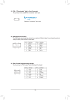
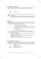
S B_ _B S S_ _ B _S _U S__ _B B SB_3 UF _ B SB3 F S S S 6) SATA3 0/1/2/3/4/5 (SATA 6Gb/s Connectors) The SATA connectors conform to SATA 6Gb/s standard and are compatible with SATA 3Gb/s and SATA 1.5Gb/s standard. Each SATA connector supports a single SATA device. The Intel® Chipset supports RAID 0, RAID 1, RAID 5, and RAID 10. RefeFr to Chapter 3, "Configuring a RAID Set," for instructions on configuring a RAID array. G.QBOFM SATA3 5 3 1 420 G.QBOFM F G.QBPOinFNMo. 1 2 Definition GND TXP 7 _0 1 3 TXN 7 1 4 GND 5 RXN 6 RXP 7 GND _0 _F To enable hot-plugging for the SATA ports, refer to Chapter 2, "BIOS Setup," "Peripherals\SATA And RST Configuration," for more information. _F _0 F 7) M2A/M2M (M.2 Socket 3 Connectors) The M.2 connectors support M.2 SATA SSDs or M.2 PCIe SSDs and support RAID configuration. Please note that an M.2 PCIe SSD cannot be used to create a RAID set either with an M.2 SATA SSD or a SATA hard drive. To create a RAID array with an M.2 PCIe SSD, you must set up the configuration in UEFI BIOS mode. Refer to Chapter 3, "Co_n0figurinFg a RAID Set," for instructions on configuring a RAID array. M2A 110 80 60 42 M2M 80 60 42 _3 U Follow the steps below to correctly install an M.2 SSD in the M.2 connector. Step 1: Locate the M.2 connector where you will install the M.2 SSD, use a screwdriver to unfasten the screw on the heatsink and then remove the heatsink. (Only the M2A connector has the heatsink) Step 2: _3 U Locate the proper mounting hole for the M.2 SSD to be installed and then tighten the standoff first. Insert the M.2 SSD into the M.2 connector at an angle. Step 3: Press the M.2 SSD down and then secure it with the screw. Replace the heatsink and secure it to the original hole. Select the proper hole for the M.2 SSD to be installed and refasten the screw and nut. - 15 -
-
 1
1 -
2
-
3
-
4
-
5
-
6
-
7
-
8
-
9
-
 10
10 -
 11
11 -
 12
12 -
 13
13 -
 14
14 -
 15
15 -
 16
16 -
 17
17 -
 18
18 -
 19
19 -
 20
20 -
21
-
22
-
23
-
24
-
25
-
26
-
27
-
28
-
29
-
30
-
31
-
32
-
33
-
34
-
35
-
36
-
37
-
38
-
39
-
40
-
41
-
42
-
43
-
44
-
45
-
46
-
47
-
48
 |
 |
