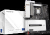
Gigabyte Z590 VISION D User Manual - Page 21
Back Panel Connectors, DisplayPort In Port, HDMI Port, SMA Antenna Connectors 2T2R
 |
View all Gigabyte Z590 VISION D manuals
Add to My Manuals
Save this manual to your list of manuals |
Page 21 highlights
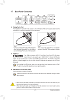
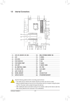
1-7 Back Panel Connectors DisplayPort In Port The DisplayPort In port offers video outputs to the motherboard. Refer to the pictures below and the Thunderbolt™ 4 Connector introduction for more information. Step 1: Connect your DisplayPort cable or Mini-DisplayPort cable (purchased separately) from the graphics card to the DisplayPort In port on the back panel. Step 2: Then connect the DisplayPort or Thunderbolt™ devices to VisionLINK TB connector to complete. HDMI Port The HDMI port supports HDCP 2.3 and Dolby TrueHD and DTS HD Master Audio formats. It also supports up to 192KHz/16bit 7.1-channel LPCM audio output. You can use this port to connect your HDMI-supported monitor. The maximum supported resolution is 4096x2160@30 Hz, but the actual resolutions supported are dependent on the monitor being used. After installing the HDMI device, make sure to set the default sound playback device to HDMI. (The item name may differ depending on your operating system.) SMA Antenna Connectors (2T2R) Use this connector to connect an antenna. Tighten the antennas to the antenna connectors and then aim the antennas correctly for better signal reception. •• When removing the cable connected to a back panel connector, first remove the cable from your device and then remove it from the motherboard. •• When removing the cable, pull it straight out from the connector. Do not rock it side to side to prevent an electrical short inside the cable connector. - 21 - Hardware Installation
-
 1
1 -
2
-
3
-
4
-
5
-
6
-
7
-
8
-
9
-
10
-
11
-
12
-
13
-
14
-
15
-
 16
16 -
 17
17 -
 18
18 -
 19
19 -
 20
20 -
 21
21 -
 22
22 -
 23
23 -
 24
24 -
 25
25 -
 26
26 -
27
-
28
-
29
-
30
-
31
-
32
-
33
-
34
-
35
-
36
-
37
-
38
-
39
-
40
-
41
-
42
-
43
-
44
-
45
-
46
-
47
-
48
-
49
-
50
-
51
-
52
-
53
-
54
-
55
-
56
-
57
-
58
-
59
-
60
-
61
-
62
-
63
-
64
-
65
-
66
-
67
-
68
-
69
-
70
-
71
-
72
-
73
-
74
-
75
-
76
-
77
-
78
-
79
-
80
-
81
-
82
-
83
-
84
-
85
-
86
-
87
-
88
-
89
-
90
-
91
-
92
-
93
-
94
-
95
-
96
-
97
-
98
-
99
-
100
-
101
-
102
-
103
-
104
-
105
-
106
-
107
-
108
-
109
-
110
-
111
-
112
 |
 |
