Haier HB2400VA1M20 User Manual
Haier HB2400VA1M20 Manual
 |
View all Haier HB2400VA1M20 manuals
Add to My Manuals
Save this manual to your list of manuals |
Haier HB2400VA1M20 manual content summary:
- Haier HB2400VA1M20 | User Manual - Page 1
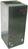
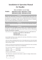
& Operation Manual Air Handler Models: 10 to 12 SEER 2 to 3.5 Tons HB2400VA1M20 HB2400VC1M20 HB3000VA1M20 HB3600VA1M20 WARNING WHEN THIS & 90B UNIFORM MECHANICAL CODE READ THESE INSTRUCTIONS COMPLETELY BEFORE ATTEMPTING TO INSTALL OR SERVICE THIS APPLIANCE. ONLY FACTORY AUTHORIZED KITS - Haier HB2400VA1M20 | User Manual - Page 2
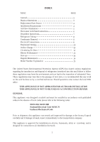
INDEX TOPIC General Physical dimensions Replacement Parts Source Installation Requirements Air Flow Orientation Horizontal Left-Hand Instructions Downflow Instructions Refrigerant Tubing Condensate Removal Electrical Connections Thermostat Wiring Orifice Change Circulating Air Duct Blower - Haier HB2400VA1M20 | User Manual - Page 3
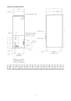
PHYSICAL DIMENSIONS D 1" C [2.54 cm] PLASTIC BREAKER COVER B E 11" [29 cm] SUCTION LINE A 3.3" [8.3 cm] PRIMARY & SECONDARY CONDENSATE DRAINS- HORIZONTAL 3/4" NPT F K G 2" [5.1 cm] 1.1" [2.9 cm] LIQUID LINE 2" [5.1 cm] TYPICAL 2.4" [ 6 cm] 1.2" [3 cm] H INLET FRONT VIEW 5" [12 - Haier HB2400VA1M20 | User Manual - Page 4
are available through local distributors.When ordering replacement parts, give the COMPLETE model and serial numbers shown product is designed for zero inch (0") clearance; however, adequate access for service or replacement must be considered without removing permanent structure. This unit can be - Haier HB2400VA1M20 | User Manual - Page 5
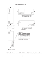
AIR FLOW ORIENTATION *Horizontal Right Discharge Tube and Drain conn. front Downflow discharge (with plastic vertical pan only) (see page 7) Horizontal Left Discharge Tube and Drain conn. front (see page 6) Important: Remove the horizontal pan when unit is installed in unconditioned i.e. (Garage, - Haier HB2400VA1M20 | User Manual - Page 6
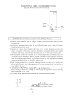
HORIZONTAL LEFT-HAND INSTRUCTIONS Important: Read instructions below carefully. Plastic Drain cover Fig.1 oval gasket WARNING sure not to over torque screws. Snap in the drain cover on the right lower service panel. 7) The Airhandler can now be placed in its left horizontal position as shown - Haier HB2400VA1M20 | User Manual - Page 7
INSTRUCTIONS Important: Read instructions panel is recommended at the point where the duct meets with the return part of the Air Handler unit to allow easier removal of coils that are AIR SIDE OF UNIT REAR CHANNELL BRACKET ZEE COIL SUPPORT BRACKET COIL RETAINING BRACKET TIE BRACKET NOTE: THE FIL - Haier HB2400VA1M20 | User Manual - Page 8
REFRIGERANT TUBING Refrigerant tubing should be installed as to avoid undue stress. They must be supported or routed to avoid strain or vibration. To avoid damage that can be caused by condensate, insulate the suction tube with a closed cell insulation with - Haier HB2400VA1M20 | User Manual - Page 9
15/15 0.9 Blower Motor H.P. 1/8 HB3000VA1M20 -------- 15/15 2.3 1/3 HB3600VA1M20 -------- 15/15 2.3 1/3 Model No. Min. Max. Blower running OF STRAIN RELIEF MUST BE INSTALLED TO THIS APPLIANCE AT THE ELECTRICAL SERVICE ENTRANCE. When an optional electric heat kit is installed refer to the - Haier HB2400VA1M20 | User Manual - Page 10
THERMOSTAT WIRING For Thermostat Control Environment-temperature and Air Conditioning open/stop, the wiring diagram as shown diagram 1. Thermostat can be mechanical type or programmable type. Note: Thermostat C : COM. R : AC24V TERMOSTAT Y : COMPRESSOR G O Y R C G : FAN O : 4 -WAY VALUE - Haier HB2400VA1M20 | User Manual - Page 11
For Thermostat Control Environment-temperature and Air Conditioning open/stop, the wiring diagram as shown diagram 4. Thermostat can be mechanical type or programmable type. Note: Thermostat C: COM. R : AC24V TERMOSTAT Y : COMPRESSOR G Y R C G : FAN For detailed Thermostat, please connect - Haier HB2400VA1M20 | User Manual - Page 12
3) Remove the check piston to verify it is correct. See piston kit chart in instructions. 4) Use a tube cutter to remove the spin closure on the suction line. & 90B and the National Environmental Systems Contractors Association Manual "K". The use of flexible duct connectors is recommended to - Haier HB2400VA1M20 | User Manual - Page 13
Pressure (inches of water column dry coil w/ filter) 4% reduction for wet coil. Model Static Pressure 0.1 CFM HB2400VA1M20 High 900 Middle 630 HB3000VA1M20 High HB3600VA1M20 Middle 0.15 877 614 1016 1276 1016 0.2 856 599 990 1244 990 0.25 835 585 965 1213 965 0.3 0.35 0.4 0.5 816 795 766 - Haier HB2400VA1M20 | User Manual - Page 14
such as carbon monoxide (CO) which may cause serious personal injury or death. REGULAR MAINTENANCE WARNING DISCONNECT ALL POWER SUPPLIES BEFORE PERFORMING ANY SERVICE. The only item to be maintained on a regular basis by the user is to insure that the circulating air filter(s) is cleaned or - Haier HB2400VA1M20 | User Manual - Page 15
-
 1
1 -
 2
2 -
 3
3 -
 4
4 -
 5
5 -
 6
6 -
 7
7 -
8
-
9
-
10
-
11
-
12
-
13
-
14
-
15
 |
 |
10 to 12 SEER
2 to 3.5 Tons
HB2400VA1M20
HB2400VC1M20
Installation & Operation Manual
Air Handler
E
WARNING
WHEN THIS APPLIANCE IS INSTALLED IN AN ENCLOSED AREA, SUCH AS
A GARAGE OR UTILITY ROOM, WITH ANY CARBON MONOXIDE PRODUCING
DEVICES (i.e. AUTOMOBILE, SPACE HEATER, WATER HEATER,ETC.) INSURE
THAT THE ENCLOSED AREA IS PROPERLY VENTILATED.
WARNING
CARBON MONOXIDE (REFERED TO AS CO) CAN CAUSE PERSONAL INJURY
OR DEATH
WARNING
FAILURE TO FOLLOW THESE INSTRUCTIONS, LOCAL CODES OR NATIONAL
CODES MAY CAUSE FIRE, EXPLOSION, ELECTRICAL SHOCK, PERSONAL
INJURY OR PROPERTY DAMAGE.
FOLLOW ALL LOCAL CODES. IN THE ABSENCE OF LOCAL CODES REFER TO :
NATIONAL ELECTRICAL CODE NFPA 70
NFPA 90A & 90B
UNIFORM MECHANICAL CODE
READ THESE INSTRUCTIONS COMPLETELY BEFORE ATTEMPTING TO INSTALL
OR SERVICE THIS APPLIANCE.
ONLY FACTORY AUTHORIZED KITS OR ACCESSORIES SHOULD BE USED WHEN
INSTALLING OR MODIFYING THIS APPLIANCE, UNLESS OTHERWISE NOTED IN
THESE INSTRUCTIONS.
SOME LOCALITIES MAY REQUIRE THE INSTALLER/SERVICER TO BE LICENSED.
IF IN DOUBT CONTACT YOUR LOCAL AUTHORITIES.
These instructions should be retained and kept adjacent to the unit for future reference.
MODEL #
HB
00VA1M20
MODEL #
HB
00VC1M20
INSTALLATION DATE
The information contained in this booklet is subject to change without notice.
No.
0010572323
HB3000VA1M20
HB3600VA1M20
Models: