Haier HB2400VA1M20 User Manual - Page 6
Horizontal Left-hand Instructions
 |
View all Haier HB2400VA1M20 manuals
Add to My Manuals
Save this manual to your list of manuals |
Page 6 highlights
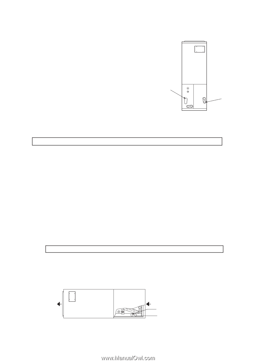
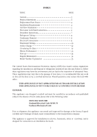
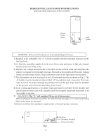
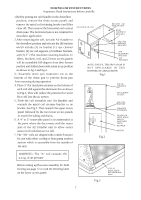
HORIZONTAL LEFT-HAND INSTRUCTIONS Important: Read instructions below carefully. Plastic Drain cover Fig.1 oval gasket WARNING: If incorrect knockouts are removed, flooding will occur. 5) Reinstall in the Airhandler, the "A" coil pan assembly with the horizontal drain pan on the left-hand side. Note: Push the assembly completely to the rear of the cavity and assure it slips into channel bracket at the rear of the cavity. 6) Replace the J-shape metal bracket or brackets on the vertical drain pan and place the plastic oval gasket on horizontal drain pan. Reinstall access panels and flowrator making sure not to over torque screws. Snap in the drain cover on the right lower service panel. 7) The Airhandler can now be placed in its left horizontal position as shown in Fig.2. The Airhandler must be leveled and then pitched 1/4" toward drain side. Important: Drain pan must be tested for proper drainage by pouring water into the pan. Traps must be installed on the primary drain and on the secondary drain if used. 8) In all cooling applications, a secondary drain pan must be provided by the installer and placed under the entire unit with a separate drain line properly sloped and terminated in an area visible to the user. 9) WARNING: The "A" coil contains 150 p.s.i.g. of air pressure. Before setting up flowrator assembly for field brazing see page 12 or read the Warning label on the lower access panel. 10) Failure to follow this installation requirements will cancel product warranty. Fig.2 6 Air flow Secondary Knockout Primary Knockout
-
 1
1 -
 2
2 -
 3
3 -
 4
4 -
 5
5 -
 6
6 -
 7
7 -
 8
8 -
 9
9 -
 10
10 -
 11
11 -
 12
12 -
13
-
14
-
15
 |
 |