Haier HBU-42HF03 User Manual - Page 23
After wiring, When wiring is not, complete
 |
View all Haier HBU-42HF03 manuals
Add to My Manuals
Save this manual to your list of manuals |
Page 23 highlights
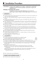
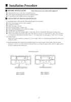
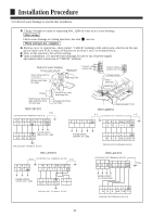
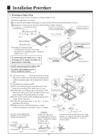
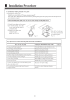
Installation Procedure (2) Check if water drainage is smooth after installation. Charge, through air outlet or inspecting hole, 1200ccd water to see water drainage. After wiring Check water drainage in cooling operation. See also 10 test run. When wiring is not complete Remove cover of control box, short connect "CHECK" terminal of the indoor unit, which is on the uper part of indoor unit PCB. Connect 1PH power to terminal 1 and 2 on terminal block. Note, in this operation, fan will be running. Upon confirmation of a smooth water drainage, be sure to cut off power supply and remove short connection of "CHECK" terminal. 1 4 5 Method of water charging Self-provided stiff pipe Maintenance Water drainage port for maintenance (Drain water from this hole) Inspecting hole Connect with outdoor unit 3 D 2 Connect with outdoor unit Terminal block PCB on indoor unit Terminal block 100mm Watering can of plastic pipe should be about 100 mm long Charge water from inspecting hole Charge water from air outlet HBU-28CF03 OUTDOOR UNIT TERMINAL BLOCK Y/G W B R Y/G W B Y/G 1 2 3 L N R S T N Cover of controll box HBU-42HF03 Y/G Y/G OUTDOOR UNIT TERMINAL BLOCK W B R B R G R Y/G L N3 4 5 1 23 POWER SUPPLY: 1PH,220-230V~,50Hz W B R Y/G POWER SUPPLY: 380-400V, 3N~, 50Hz INDOOR UNIT TERMINAL BLOCK HBU-28HF03 Y/G OUTDOOR UNIT TERMINAL BLOCK Y/G W B Y/G L N W B R B R G R Y/G 1 2 3 4 5 POWER SUPPLY: 1PH,220-230V~,50Hz 1 23 W B R Y/G 4 5 INDOOR UNIT TERMINAL BLOCK 1234 5 W B R B R G R Y/G INDOOR UNIT TERMINAL BLOCK HBU-42CF03 OUTDOOR UNIT TERMINAL BLOCK R S TN 1 2 3 Y/G POWER SUPPLY: 3N~,380-400V,50Hz 1234 5 W B R B R G R Y/G INDOOR UNIT TERMINAL BLOCK 21
-
 1
1 -
2
-
3
-
4
-
5
-
6
-
7
-
8
-
9
-
10
-
11
-
12
-
13
-
14
-
15
-
16
-
17
-
 18
18 -
 19
19 -
 20
20 -
 21
21 -
 22
22 -
 23
23 -
 24
24 -
 25
25 -
 26
26
 |
 |