Haier HC36D1VAR User Manual - Page 12
Electrical Wiring
 |
View all Haier HC36D1VAR manuals
Add to My Manuals
Save this manual to your list of manuals |
Page 12 highlights
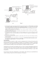
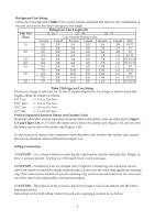
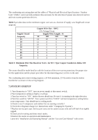
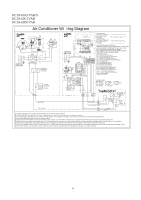
1.Fully open both shutoff valves. 2.Connect service gage manifold to the valve service ports, being sure to evacuate lines. 3.Startup the system (Refer to the Section 7 - "System Startup"). Run system at least 10 minutes to allo System Superheat Ambient Return Air Temperature ( F) Temperature At 65 70 75 80 85 Condenser Inlet ( F) 60 17 25 30 33 37 pressure to stabilize. 65 13 19 26 32 35 4.Temporarily install thermometer on suction (large) 70 5 14 20 28 32 line near condensing unit. Be sure of good contact 75 5 10 17 25 29 between thermometer and line. Wrap thermometer 80 5 12 21 26 with insulating material to assure accurate reading. 85 5.Refer to Table 8 for proper system superheat. Add 90 charge to lower superheat. Remove charge to raise 95 superheat. 100 5 10 7 5 17 20 12 18 5 5 5 5 Carefully remove gage lines. Table 8:System charging table by superheat 6.4.ELECTRICAL WIRING ! WARNING - A means of strain relief must be installed to this appliance at the electrical service entrance. Make sure that interconnecting wires between indoor and outdoor units meet the standards, codes and regulations. Incomplete connection or fixing of the wire could result in a fire. A means of strain relief must be installed to this appliance at the electrical service entrance. Do not use intermediate connection of the power cord or the extension cord and do not connect many devices to one AC outlet. It could cause a fire or an electric shock due to defective contact, defective insulation, exceeding the permissible current, etc. Perform electrical work according to the installation manual and be sure to use an exclusive circuit. If the capacity of the power circuit is insufficient or there is incomplete electrical work, it could result in a fire or an electric shock. Ground the unit. Do not connect the ground to a gas pipe, water pipe, lighting rod or telephone ground. Defective grounding could cause an electric shock. Electrical installation will consists of power supply wiring to the condensing unit and control wiring between thermostat, indoor unit and the condensing unit. All wiring must be in accordance with National Electrical Code and/or local ordinances that may apply. (See unit wiring diagram furnished with this instruction). Note: Some states need the power supply wiring within special tybe be careful to use the waterproof tube when installation the outdoor unit power supply wiring.(See the figure 4) Figure 4-1 10 Figure 4-2
-
 1
1 -
2
-
3
-
4
-
5
-
6
-
 7
7 -
 8
8 -
 9
9 -
 10
10 -
 11
11 -
 12
12 -
 13
13 -
 14
14 -
 15
15 -
 16
16 -
 17
17
 |
 |
