Haier HSU-24LEA03 User Manual - Page 2
Parts and Functions
 |
View all Haier HSU-24LEA03 manuals
Add to My Manuals
Save this manual to your list of manuals |
Page 2 highlights
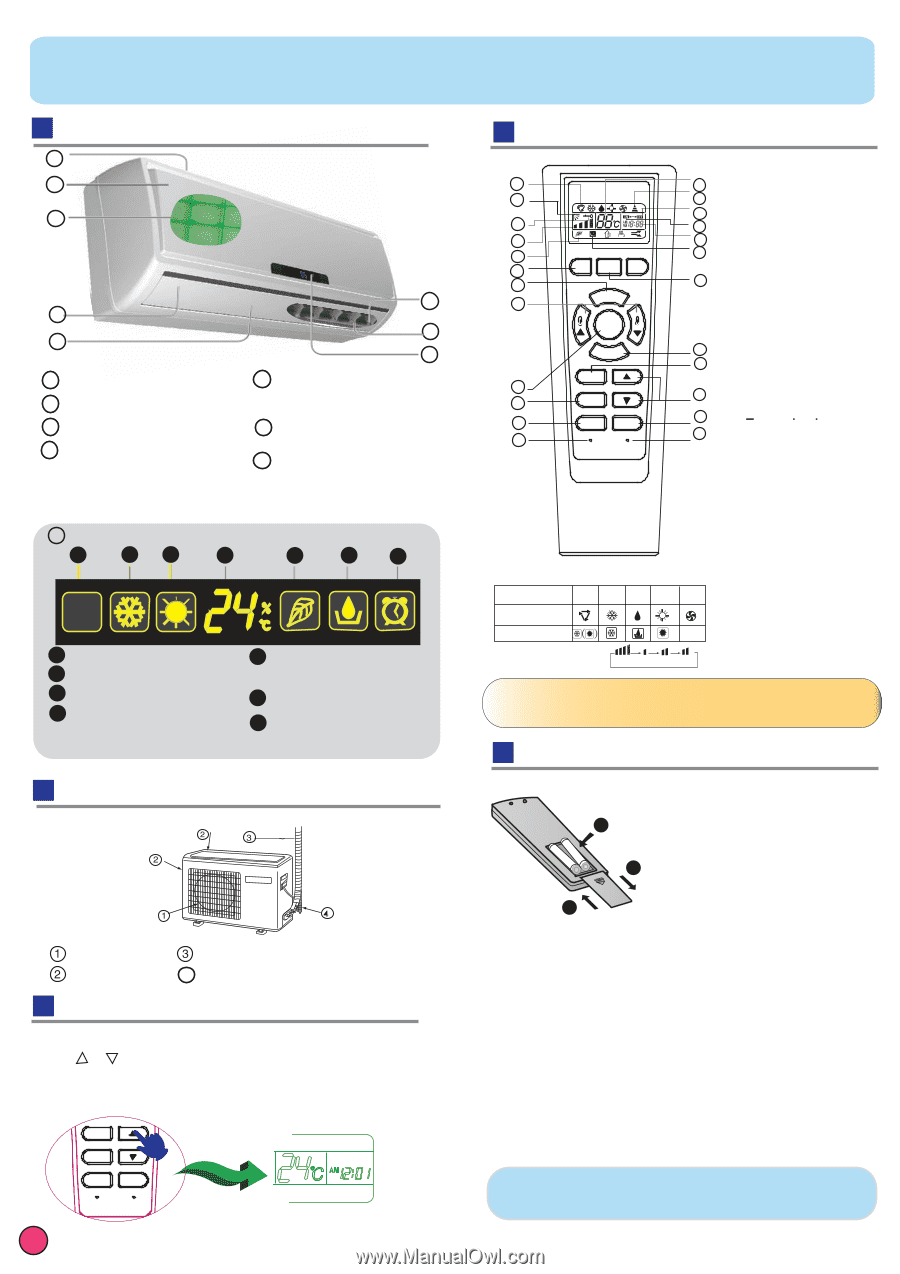
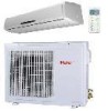
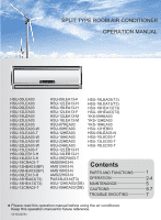
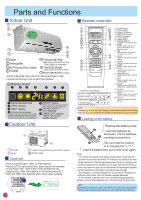
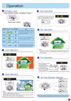
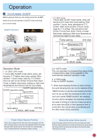
Parts and Functions Indoor Unit 1 2 3 45 7 6 5 8 1 Inlet 2 Inlet grille 3 Air Purifying Filter (inside) 54 Outlet 45 Horizontal flap (adjust up and down air flow Don't adjust it manually) 6 Vertical blade (adjust left and right air flow) 7 Anion generator (inside) Actual inlet grille may vary from the one shown in the manual according to the product purchased 8 Display board 1 23 4 5 6 7 1 Signal receiver hole 2 COOL display 3 HEAT display 4 Ambient temp.display When receiving the remote control signal, display the set temperature and in the rest time the room temperature is displayed and this room temperature is only for reference. 5 HEALTH display (If the unit which you purchased has healthy function,follow it. 6 If not,please ignore.) Dry display 7 TIMER OFF display TIMER ON display SLEEP display Outdoor Unit OUTLET INLET CONNECTING PIPING AND ELECTRICAL WIRING 14 DRAIN HOSE Clock set Press CLOCK button, "AM" or "PM" flashes. Press or to set correct time. Each press will increase or decrease 1min. If the button is kept pressed,time will change quickly. After time setting is confirmed,press SET, "AM "and "PM" stop flashing,while clock starts working. TIMER CLOCK SET SLEEP LOCK RESET 1 Remote controller 1 10 2 6 7 5 8 3 9 23 HEALTH ON/OFF 4 23 13 11 FAN 18 MODE SWING 15 20 TIMER 12 21 CLOCK 14 19 16 SET SLEEP 22 17 LOCK RESET 1. Operation mode display Operation mode AUTOCOOLDRYHEAT FAN Remote controller Display board 2. SWING display 3. FAN SPEED display AUTO LO MED HI 4. SLEEP display 5. LOCK display 6. SIGNAL SENDING 7.TIMER OFF display 8. TIMER ON display 9. CLOCK display 10. TEMP display 11. POWER ON/OFF Used for unit start and stop. 12. MODE Used to select AUTO run, COOL,DRY,HEAT and FAN operation 13. FAN Used to select fan speed LO, MED, HI, AUTO 14. HOUR Used to set clock and timer setting. 15. SWING Used to set auto fan direction. 16. SLEEP Used to select sleep mode. 17. LOCK Used to lock buttons and LCD display. 18. TEMP.SETTING Used to select your desired temp. 19. SET Used to confirm timer and clock settings. 20. TIMER Used to select TIMER ON, TIMER OFF,TIMER ON-OFF 21. CLOCK Used to set correct time 22. RESET Used to reset the controller back to normal condition. 23. HEALTH Used to operate the healthy fu. nction NOTE: Cooling only unit do not have displays and functions related with heating If the unit which you purchased has healthy function,follow it.If not,please ignore. Loading of the battery 1 Remove the battery cover; 2 2 Load the batteries as illustrated. 2 R-03 batteries, 1 resetting key(cylinder); 3 3Be sure that the loading is in line with the " + "/"-"; 4 Load the battery,then put on the cover again. Note: The distance between the signal transmission head and the receiver hole should be within 7m without any obstacle as well. When electronic-started type fluorescent lamp or change-over wireless telephone is installed in the type fluorescent lamp or room, the receiver is apt to be disturbed in receivingthe signals, so the distance to the indoor unit should be shorter. Full display or unclear display during operation indicates the batteries have been used up.Please change batteries. If the remote controller can't run normally during operation, please remove the batteries and reload several minutes later. Hint: Remove the batteries in case unit won't be in usage for a long period. If there are any display after taking-out, just need to press reset key
-
 1
1 -
 2
2 -
 3
3 -
 4
4 -
 5
5 -
 6
6 -
 7
7 -
 8
8
 |
 |