Haier HWM65-23BS User Manual - Page 7
How to change the direction of the drain hoses
 |
View all Haier HWM65-23BS manuals
Add to My Manuals
Save this manual to your list of manuals |
Page 7 highlights
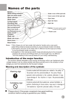
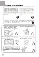
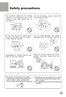
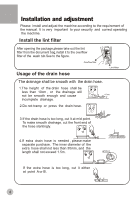
How to change the direction of the drain hoses Figure 1 indicates the ex factory installation position of the drain hose. Soft item Extend the drain hose from the side of spin tub Put soft items on the ground. Lean the machine down gently with the front surface facing the ground. Take off the drain hose from the cabinet. Take the hose out of the fixing groove. (See to Figure 2). Embed the drain hose into the groove along the Soft item side of the spin tub in the order of (1)~(3), heading for the side of the spin tub. (See to Figure 3). Embed the drain hose into the groove with hands. Take care not to damage the drain hose in fastening the fixing clamp. Extend the drain hose from the rear side Extend to the spin tub side Take out the drain hose from the fixing groove. Extend it fromthe rear side as per the direction of the arrow. (When the drainhose is extended from the rear side, it can be hung on the point for drain hose at the two sides of the cabinet.) (See to Figure 4). Back Front Figure 1 Figure 2 Embed into the groove in turn Figure 3 Figure 4 Install the water inlet hose; Quick water-filling entrance Select the water level Please fix water inlet hose according to the fact of the washing machine model which you bought. Figure 1 shows the frame of the control panel Water inlet hose Water inlet jointer Insert the water inlet hose into the water-filling entrance on the control pane directly.(pull it out to dismantle it) Water inlet hose Push Control handle Water inlet Figure 2 shows the frame of the control panel Water inlet Insert the water inlet hose into the water- filling entrance on the control panel, then push the water-filling jointer into the entrance on the control panel. (To dismantle the water inlet pipe,just push the control handle as indicated in the figure and pull it out) Figure 1 Maximum Max Select water level according to the quantity of the laundries. Med Medium Min Minimum Set the water level adjusting lever to needed line. Figure 2 Water level indicator
-
 1
1 -
 2
2 -
 3
3 -
 4
4 -
 5
5 -
 6
6 -
 7
7 -
 8
8 -
 9
9 -
 10
10 -
 11
11 -
 12
12 -
13
-
14
-
15
-
16
-
17
-
18
 |
 |
