Haier HWR10XC5 User Manual - Page 16
Installing Unit into A Window - window air conditioner
 |
UPC - 688057343365
View all Haier HWR10XC5 manuals
Add to My Manuals
Save this manual to your list of manuals |
Page 16 highlights
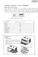
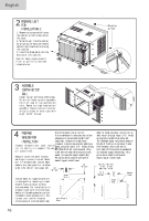
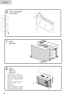
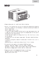
English Installing Unit into A Window Window Opening Requirements The air conditioner is designed to fit into double or single hung sash type wi units comes with an installation kit that provides adjustable mounting louvers between the sides of the unit, and the window frame. The chart below reflects the units with, and without installation kits. Measure your window opening it to the chart below to ensure that it meets the minimum and maximum window width requirem B C A D HWR10XC5, HWR12XC5,ESA3105, ESA3125 Model Dimension A(inch) B(inch) C(inch) D(inch) Max D(inch) Min Case High Case Width Case Depth HWR10XC5, HWR12XC5, ESA3105, ESA3125 8 21 32 " 15 9 16 " 15 15 16 " 39 " 27 " 14 31 32 " 23 5 8 " 22 7 16 " edoM 1 PREPARE UNIT FOR INSTALLATION-1 Unpack unit on floor next to installation location. 1. Open the inlet grille by pulling the exposed door on the top of the unit and remove the screw which fasten the front panel. (Fig. A) 2. Remove the front panel and rotate it to B position. Separate operation panel from the front panel by pushing the tabs. (Fig. B) Fig. A Tabs Fig. B
-
 1
1 -
2
-
3
-
4
-
5
-
6
-
7
-
8
-
9
-
10
-
 11
11 -
 12
12 -
 13
13 -
 14
14 -
 15
15 -
 16
16 -
 17
17 -
 18
18 -
 19
19 -
 20
20 -
 21
21 -
22
-
23
 |
 |
