Haier QSS740RNSS Installation Instructions - Page 1
Haier QSS740RNSS Manual
 |
View all Haier QSS740RNSS manuals
Add to My Manuals
Save this manual to your list of manuals |
Page 1 highlights
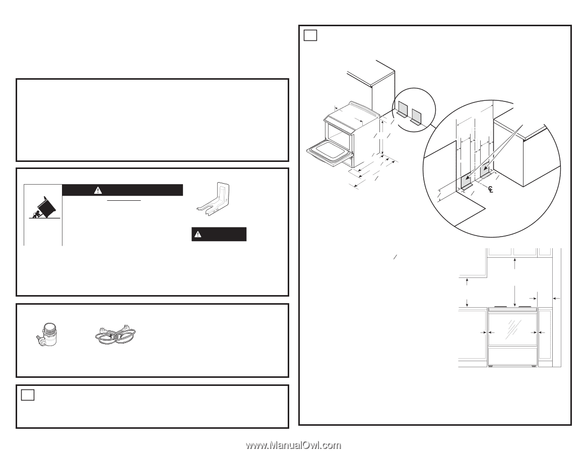
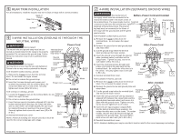
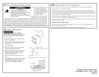
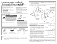
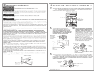
Installation Instructions Electric Slide-In Ranges Questions? Visit cafeappliances.com. In Canada, visit cafeappliances.ca. BEFORE YOU BEGIN Read these instructions completely and carefully. • IMPORTANT - Save these instruc- tions for local inspector's use. • IMPORTANT - Observe all governing codes and ordinances. • Note to Installer - Be sure to leave these instructions with consumer. • Note to consumer - Keep these instructions for future reference. • Skill level - Installation of this appliance requires a qualified installer or electrician. • Proper installation is the responsibility of the installer. • Product failure due to improper installation is not covered under warranty. FOR YOUR SAFETY: WARNING Tip-Over Hazard • A child or adult can tip the range and be killed. • Install the anti-tip bracket to the wall or floor. • Engage the range to the anti-tip bracket by sliding the range back such that the foot is engaged. • Re-engage the anti-tip bracket if the range is moved. • Failure to do so can result in death or serious burns to children or adults. If you did not receive an anti-tip bracket with your purchase, visit cafeappliances.com (In Canada, cafeappliances.ca). Anti-Tip Bracket Kit Included WARNING Before beginning the installation, switch power off at service panel and lock the service disconnecting means to prevent power from being switched on accidentally. When the service disconnecting means cannot be locked, securely fasten a prominent warning device, such as a tag, to the service panel. MATERIALS YOU MAY NEED Squeeze Connector (For Conduit Instal- lations Only) (UL Listed 40 AMP) 4-Wire Cord 4' long OR 3-Wire Cord 4' long TOOLS YOU WILL NEED Drill with 1/8" Bit Safety Glasses Adjustable Wrench Level Tin Snips Tape Measure Pliers 1/4" Nut Driver 1 REMOVE PACKAGING MATERIALS: Failure to remove packaging materials could result in damage to the appliance. Remove all packing parts from oven, racks, heating elements and drawer. Also, remove protective film and labels on the outer door, cooktop and control panel. 2 PREPARE THE OPENING (FOR INDOOR USE ONLY) See illustrations for all rough-in and spacing dimensions. The range may be placed with 0" clearance (flush) at the back wall and side walls of the cabinet. 30" 11»8" 361»4" ± 1»4" 271»4" w/o handle 291»4" with handle 473»4" Install the outlet box on either side of the CL 30" 3" 3" 3" 4" 9" 8" Recommended acceptable electrical outlet area. Orient the electrical receptacle so the length is parallel to the floor. 71»2" 21»4" 21»4" NOTE: Use a 4' power cord to prevent interference with the storage drawer. Power cords 41» ' 2 to 6' long may have to be dressed to allow for proper drawer closing. MINIMUM DIMENSIONS BETWEEN COOKTOP, WALLS AND ABOVE THE COOKTOP: A. Make sure the wall covering, countertop, flooring and C cabinets around the range can withstand the heat (up to 200°F) generated by the range. 0" to cabinets below cooktop and at the range back. B C Both Sides B. Allow 30" minimum clearance between surface units and bottom of unprotected wood or metal cabinet, or allow a 24" minimum when bottom of wood or metal A A cabinet is protected by no less than 1/4" thick flame retardant millboard covered with not less than No. 28 MSG sheet metal, (.015"), .015" thick stainless steel, .024" aluminum or .020" copper. C. This appliance has been approved for 0" spacing to adjacent surfaces above the cooktop. However, a 6" minimum spacing to surfaces less than 15" above the cooktop and adjacent cabinet is recommended to reduce exposure to steam, grease splatter and heat. To reduce the risk of burns or fire when reaching over hot surface elements, cabinet storage space above the cooktop should be avoided. If cabinet storage space is to be provided above the cooktop, the risk can be reduced by installing a range hood that projects at least 5" beyond the front of the cabinets. Cabinets installed above the cooktop must be no deeper than 16".
-
 1
1 -
 2
2 -
 3
3 -
 4
4 -
 5
5 -
 6
6 -
 7
7 -
8
 |
 |