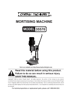
Harbor Freight Tools 35570 User Manual - Page 5
Assembly Instructions, Operating Procedures
 |
View all Harbor Freight Tools 35570 manuals
Add to My Manuals
Save this manual to your list of manuals |
Page 5 highlights
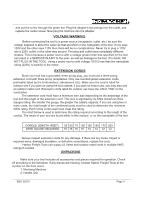
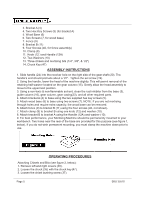
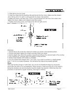
3. Bracket A (4) 4. Two Hex Key Screws (5) (for bracket A) 5. Wood Base (6) 6. Two Screws (7, for wood base) 7. Fence (9) 8. Bracket B (11) 9. Four Screws (40, for fence assembly) 10. Clamp (8) 11. Knob (12 ) and Handle (12A) 12. Two Washers (10) 13. Three chisels and mortising bits (1/4", 3/8", & 1/2") 14. Chuck Key (47) ASSEMBLY INSTRUCTIONS 1. Slide handle (24) into the receiver hole on the right side of the gear shaft (20). The handle's end should protrude about a 1/2". Tighten the set screw (19). 2. Using the handle, lower the head of the machine slightly. This will permit removal of the retaining half-washer located on the gear column (15). Gently allow the head assembly to move to the uppermost position. 3. Using a non-toxic & non-flammable solvent, clean the rust inhibitor from the base (3), guide column (16), gear column, gear casing(23), and all other required parts. 4. Attach bracket A (4) to base using the two supplied hex key screws (5). 5. Attach wood base (6) to base using two screws (7). NOTE: If you are not mortising through holes and require extra capacity, the wood base can be removed. 6. Attach fence (9) to bracket B (11) using the four screws (40, not shown). 7. Attach clamp (8) to bracket B using one knob (12) and washer (10). 8. Attach bracket B to bracket A using the Handle (12A) and washer (10). 9. For best performance, your Mortising Machine should be permanently mounted to your workbench. Two holes near the rear of the base are provided for this purpose (see figure 1, below). If you do not wish permanent mounting, you must clamp the machine down prior to use. OPERATING PROCEDURES Attaching Chisels and Bits (see figure 2, below): 1. Remove left and right covers (39). 2. Loosen the chuck (35) with the chuck key(47). 3. Loosen the chisel bushing screw (37). Page 5 SKU 35570
-
 1
1 -
 2
2 -
 3
3 -
 4
4 -
 5
5 -
 6
6 -
 7
7 -
 8
8 -
 9
9 -
 10
10 -
 11
11
 |
 |
