Harbor Freight Tools 61972 User Manual
Harbor Freight Tools 61972 - 10 in. Sliding Compound Miter Saw Manual
 |
View all Harbor Freight Tools 61972 manuals
Add to My Manuals
Save this manual to your list of manuals |
Harbor Freight Tools 61972 manual content summary:
- Harbor Freight Tools 61972 | User Manual - Page 1
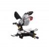
manual and the receipt in a safe and dry place for future reference. ITEM 61972 10" SLIDING COMPOUND MITER SAW WITH LASER GUIDE SYSTEM REV 14f Note: Blade sold separately. Visit our website at: http://www.harborfreight.com Email our technical support for assembly and service may not be - Harbor Freight Tools 61972 | User Manual - Page 2
Safety Table of Contents Safety 3 Setupp 7 Specifications 7 Operationa 10 Maintenancei 13 Parts List and Diagram 18 Warranty 20 WARNING SYMBOLS AND DEFINITIONS This is the safety alert symbol. It is used to alert you to potential personal injury hazards. Obey all safety messages that - Harbor Freight Tools 61972 | User Manual - Page 3
clean for best and safest performance. Follow instructions for lubricating and changing accessories. 8. USE heavier the cord. 15. DISCONNECT TOOLS before servicing; when changing accessories, such as blades, RECOMMENDED ACCESSORIES. Consult the owner's manual for recommended accessories. The use - Harbor Freight Tools 61972 | User Manual - Page 4
TO PREVENT ELECTRIC SHOCK AND DEATH FROM INCORRECT GROUNDING WIRE CONNECTION READ AND FOLLOW THESE INSTRUCTIONS: 110-120 VAC Double Insulated Tools: Tools with Two Prong Plugs Outlets for 2-Prong Plug 1. To reduce the risk of electric shock, double insulated equipment - Harbor Freight Tools 61972 | User Manual - Page 5
Setup Miter Saw Safety Warnings For Your Own Safety Read Instruction Manual Before Operating Miter Saw 1. Wear eye protection. 2. by the manufacturer may result in a risk of injury to persons. 17. When servicing use only identical replacement parts. 18. Do not depress the spindle lock when - Harbor Freight Tools 61972 | User Manual - Page 6
et seq.) 27. The warnings, precautions, and instructions discussed in this instruction manual cannot cover all possible conditions and situations that may a doctor and then have regular medical check‑ups to ensure medical problems are not being caused or worsened from use. Pregnant women or people - Harbor Freight Tools 61972 | User Manual - Page 7
Safety Specifications Motor Arbor Diameter Recommended Blade Type Blade Diameter Cutting Capacity Positive Table Stops Positive Bevel Stops Blade Tilt Range Scale 120 VAC / 60 Hz / 15 A 5,000 RPM 5/8″ General Purpose with Carbide Tips 10″ At 90°: 2-3/4″ Deep x 12″ Wide. At 45° 1-9/16″ Deep x - Harbor Freight Tools 61972 | User Manual - Page 8
Bag Blade Hold Down Clamp Miter Handle Kerf Board Table Miter Lock Handle Miter Angle Indicator Figure A: Components Bevel Angle Indicator Fence Work piece Extension Support Operation Maintenance Page 8 For technical questions, please call 1-888-866-5797. ITEM 61972 - Harbor Freight Tools 61972 | User Manual - Page 9
the parts listed in the following pages, refer to the Assembly Diagram near the end of this manual. Assembly Attaching the Extension Supports and Miter Lock Handle 1. Insert the ends of the Extension Supports into the holes in the sides of the Base. Tighten the Wing Screws to hold the Extensions - Harbor Freight Tools 61972 | User Manual - Page 10
Safety Operating Instructions Read the ENTIRE IMPORTANT SAFETY INFORMATION section at the beginning of this manual including all text during the cutting operation. 3. Use a saw table, saw stand or other means to support the work piece. The Miter Saw must be mounted in such a way that the surface - Harbor Freight Tools 61972 | User Manual - Page 11
work piece. 4. If the work piece is not level, you will make an unintentional bevel cut in the material. If the work piece is not supported, it will bind the blade and may cause the material to kick back, potentially causing injury. Adjusting the Miter Angle 1. A miter cut is one that - Harbor Freight Tools 61972 | User Manual - Page 12
manual. Making a Cut 1. Observe all safety and planning items 6. discussed in this booklet. Detailed instructions accuracy of the Guide Fence, miter angle and bevel angle. Instructions for checking and material is level and supported securely, using saw horses or supports if necessary. Grip the - Harbor Freight Tools 61972 | User Manual - Page 13
Safety Maintenance and Servicing Procedures not specifically explained in this manual must be performed only by a qualified not use damaged equipment. If abnormal noise or vibration occurs, have the problem corrected before further use. Cleaning, Maintenance, and Lubrication 1. BEFORE EACH - Harbor Freight Tools 61972 | User Manual - Page 14
Safety Replacing the Blade WARNING TO REDUCE RISK OF SERIOUS INJURY: Return guard to original position and secure in place after replacing blade. Note: Blade sold separately. 1. Unplug the tool from its power source. 2. Lock the blade assembly in the raised position by pushing in the Locking Pin. - Harbor Freight Tools 61972 | User Manual - Page 15
Safety Setup Adjusting the Fence The Fence holds the work piece in a fixed position while the Table and or the blade assembly are adjusted in a miter or bevel angle. To make accurate cuts, the Fence must be perpendicular (at a 90º angle) to the Saw Blade. 1. Before beginning work, make a test cut - Harbor Freight Tools 61972 | User Manual - Page 16
Safety Troubleshooting Problem Tool will not start Tool operates sporadically or at supported on both ends. 2. Check condition of material and check compatibility of blade to material. Follow all safety precautions whenever diagnosing or servicing the tool. Disconnect power supply before service - Harbor Freight Tools 61972 | User Manual - Page 17
PLEASE READ THE FOLLOWING CAREFULLY THE MANUFACTURER AND/OR DISTRIBUTOR HAS PROVIDED THE PARTS LIST AND ASSEMBLY DIAGRAM IN THIS MANUAL AS A REFERENCE TOOL ONLY. NEITHER THE MANUFACTURER OR DISTRIBUTOR MAKES ANY REPRESENTATION OR WARRANTY OF ANY KIND TO THE BUYER THAT HE OR SHE IS - Harbor Freight Tools 61972 | User Manual - Page 18
Safety Setup Parts List and Diagram Parts List Part Description 1 Bolt M6x25 2 Base 3 Extension Arm 4 Screw 5 Foot 6 Bolt M8x50 7 Bolt M5x10 8 Spring Washer 9 Flat Washer 10 Plate 11 Rub Slice 12 Pin 13 Spring 14 Pin 3x20 15 Handle 16 Plate 17 Extend Pole 18 Pointer 19 Bolt M4x12 20 Bolt M4x8 21 - Harbor Freight Tools 61972 | User Manual - Page 19
Safety Setup Assembly Diagram 99 112 111 103102 101 100 99 898 97 9695 94 93 112 92 91 113 108 107 106 105 104 67 64 65 67 68 65 66 33 89 90 37 63 20 54 53 119 118 117 116 115 88 114 113 87 86 85 84 83 81 80 79 82 78 76 8 77 75 120 121 122 123 124 125 126 127 2930 73 31 30 - Harbor Freight Tools 61972 | User Manual - Page 20
Limited 90 Day Warranty Harbor Freight Tools Co. makes every effort to assure that its products meet high quality and durability standards, and warrants to the original purchaser that this product is free from defects in materials and workmanship for the period of 90 days from the date of purchase.
-
 1
1 -
 2
2 -
 3
3 -
 4
4 -
 5
5 -
 6
6 -
 7
7 -
8
-
9
-
10
-
11
-
12
-
13
-
14
-
15
-
16
-
17
-
18
-
19
-
20
 |
 |
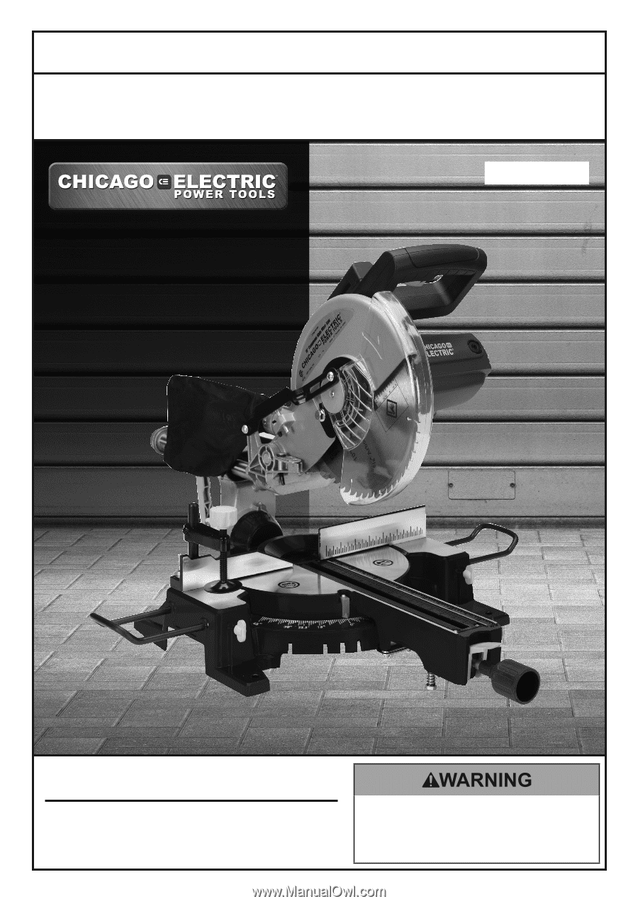
Note: Blade sold separately.
Visit our website at: http://www.harborfreight.com
Email our technical support at: [email protected]
ITEM 61972
10" SLIDING COMPOUND
MITER SAW
WITH LASER GUIDE SYSTEM
Read this material before using this product.
Failure to do so can result in serious injury.
SAVE THIS MANUAL.
Copyright
©
2013 by Harbor Freight Tools
®
.
All rights reserved.
No portion of this manual or any artwork contained herein may be reproduced in
any shape or form without the express written consent of Harbor Freight Tools.
Diagrams within this manual may not be drawn proportionally.
Due to continuing
improvements, actual product may differ slightly from the product described herein.
Tools required for assembly and service may not be included.
When unpacking, make sure that the product is intact
and undamaged.
If any parts are missing or broken,
please call 1-888-866-5797 as soon as possible.
Save This Manual
Keep this manual for the safety warnings and precautions, assembly, operating,
inspection, maintenance and cleaning procedures.
Write the product’s serial number in the back of the manual
near the assembly diagram (or month and year of purchase if product has no number). Keep this manual and
the receipt in a safe and dry place for future reference.
Owner’s Manual & Safety Instructions
REV 14f