Harbor Freight Tools 68148 User Manual - Page 8
Specifications, Unpacking, Instructions For Putting Into Use
 |
View all Harbor Freight Tools 68148 manuals
Add to My Manuals
Save this manual to your list of manuals |
Page 8 highlights
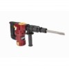
SPECIFICATIONS Electrical Input 120 V~ / 60 Hz / 10 A Blows Per Minute 3100 BPM Chisels 1 Bull Point (included) 1 Flat Point 1 Oil Bottle Other 1 Carbon Brush Set Accessories 1 5mm Hex Key 1 Oil Tank Wrench UNPACKING When unpacking, make sure the item is intact and undamaged. If any parts are missing or broken, please call Harbor Freight Tools at 1‑800‑444‑3353 as soon as possible. INSTRUCTIONS FOR PUTTING INTO USE Read the ENTIRE IMPORTANT SAFETY INFORMATION section at the beginning of this manual including all text under subheadings therein before set up or use of this product. Note: For additional information regarding the parts listed in the following pages, refer to the Assembly Diagram near the end of this manual. Functions Use Figure 1 below as reference during Tool Setup and Operation. Trigger (69) Main Handle (74) Carbon Brush Cap (54) Page 8 Oil Tank Cover (12) Chuck (35) Side Handle (62) Flat Chisel Figure 1 For technical questions, please call 1-800-444-3353. SKU 68148
-
 1
1 -
2
-
 3
3 -
 4
4 -
 5
5 -
 6
6 -
 7
7 -
 8
8 -
 9
9 -
 10
10 -
 11
11 -
 12
12 -
 13
13 -
14
 |
 |
