Harbor Freight Tools 69667 User Manual - Page 6
Functions
 |
View all Harbor Freight Tools 69667 manuals
Add to My Manuals
Save this manual to your list of manuals |
Page 6 highlights
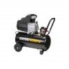
SAFETY Specifications Electrical Rating Air Outlet Size Air Pressure Shut-off Restart Air Tank Capacity Air Flow Capacity Oil Capacity Oil Type Sound Level 120V~ / 60Hz / 12A 1/4″ -18 NPT 125 PSI 95 PSI 8 Gallons 4.5 CFM @ 90 PSI 5.5 CFM @ 40 PSI 12 oz. SAE 30W, non‑detergent, Air Compressor Oil (sold separately) 88 dB @ 3' SETUP OPERATION Instructions for putting into use 226892 Read the ENTIRE IMPORTANT SAFETY INFORMATION section at the beginning of this manual including all text under subheadings therein before set up or use of this product. TO PREVENT SERIOUS INJURY FROM ACCIDENTAL OPERATION: Turn the Power Switch "OFF" and unplug the Air Compressor from its electrical outlet before assembling or making any adjustments to the compressor. Note: For additional information regarding the parts listed in the following pages, refer to the Assembly Diagram near the end of this manual. Functions Tank Output Pressure Pressure Gauge Gauge Oil Sight Glass Safety Valve Air Output Coupler Pressure Regulator (Top View) Pressure Switch OFF ON/OFF Power Lever ON Tank Pressure Gauge Output Pressure Gauge Pressure Regulator Drain Valve Figure A MAINTENANCE Page 6 For technical questions, please call 1-800-444-3353. Item 69667
-
 1
1 -
 2
2 -
 3
3 -
 4
4 -
 5
5 -
 6
6 -
 7
7 -
 8
8 -
 9
9 -
 10
10 -
 11
11 -
 12
12 -
13
-
14
-
15
-
16
-
17
-
18
-
19
-
20
 |
 |
