Harman Kardon AB 2 Owners Manual - Page 2
Amplified In-Wall Module - specification
 |
View all Harman Kardon AB 2 manuals
Add to My Manuals
Save this manual to your list of manuals |
Page 2 highlights
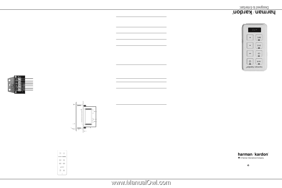
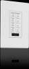
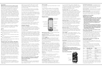
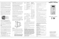
When making the connections at each end of the cable, strip the outer insulation jacket about 1-1/2" to 2" from the end. The cable is constructed of four twisted pairs of wires, as indicated above. Flatten the wire ends to prepare them for insertion into the connector. Fully insert the wire into the connector, being certain to check the color codes of the pin assignments one last time. Carefully crimp the connector, making sure that each wire is securely fastened. Step Three: Connect the Category 5/5e cable to the AB 2. Once the wire is run to the remote location where the AB 2 will be installed, connect the Category 5/5e cable to the AB 2. Prior to making the connections, strip the outer jacket of the Cat. 5/5e cable 1-1/2" to 2" from the end, taking care not to nick the inner conductors. Next, separate the four twisted pairs within the cable and then untwist the ends of each pair about 1/2." All terminations are made at the Input-Cable Connection Block. Connect the wires using standard 110 Insulation Displacement Connector (IDC) tools and procedures. DO NOT use screwdrivers to insert the wire into the IDC connection points. Make certain that there are no shorts between any of the individual wires, as this may cause damage to the AB 2. From left to right, the connections are made as indicated in the figure below. Brown Brown and White Blue Blue and White Green Green and White Orange Orange and White Step Four: Connect the speaker cable to the AB 2. Connect speaker wires to the AB 2 module using the colorcoded chart on the Speaker Terminal Block as a guide. Observe the positive (+) and negative (-) polarity indications, and avoid having the wire strands from one cable touch another. Loosen the retaining screws on the Speaker Terminal Block and insert the wire into the appropriate slots. Tighten the retaining screws to secure the wire. Step Five: Connecting the AB 2 to the A-BUS-equipped product. After making certain that the connections to the speaker cable and Cat. 5/5e cable have been made properly, plug the RJ-45 jack at the receiver end of the cable into the A-BUS jack on the back of the A-BUS-equipped product, and connect its IR output to the source device's IR input, daisychaining for more than one source. Next, turn on the receiver or other source and turn on the Multiroom system. As a confirmation that the system connections have been made, the Status LED will light. When the AB 2 is turned on by pressing a source selector or using a remote control to issue an IR command, the red LED on the Power Off key will light, and a green LED will indicate the current source. Step Six: Adjust the output levels. This step sets the level adjustments for the AB 2. Once this process is complete, all further volume settings are made with the Volume Up/Down Buttons on the AB 2, the included remote, or any compatible third-party remote. With the Multiroom system activated and a source playing, press the Volume Up Button for 20 seconds so that the AB 2's volume is set at its maximum. Next, adjust each of the Output-Level Trims until the output begins to clip. At this point, back the trim control down in the opposite direction until the clipping stops. This is the correct level for your specific A-BUSequipped product and the AB 2. Before proceeding further, lower the volume back to normal listening level. Step Seven (Optional): Switch keypads. You may switch keypads to better reflect the source devices connected to the ABH 4000 or other multizone hub. The Power Off/Mute, Skip Up/Down and Volume Up/Down keys remain the same, but the source names change from AVR to TN (tuner), CD to SAT, DVD to VID, and MP3 to The Bridge icon. Note, however, that The Bridge may only be connected to a Harman Kardon A-BUS-equipped product, and may only be selected as a playback source by pressing and holding the AVR Button on the AB 2 keypad. To switch keypad sets, remove the AB 2's white front panel by gently pressing the four clips that secure it to the back of the metal chassis. Be gentle so as not to inadvertently break off the clips. The entire keypad set may be removed and replaced, with the small holes on the sides of the keypad frame fitting over the corresponding pins on the back of the AB 2 front panel. When replacing the front panel, orient it so that the red lens fits over the red LED on the chassis. Step Eight: Install the AB 2. Place the AB 2 in the junction box or plaster ring, making sure that any loose wire is carefully secured inside the wall or box, and that there are no shorts between any of the connections. Using the supplied mounting screws, attach the AB 2 to the junction box or plaster ring through the Screw Slots. Attach a Decora-style wall plate (not included) through the AB 2's Screw Holes. Although any color Decora wall plate may be used with the AB 2, the AB 2 itself should not be painted. Front Panel SpeakerTerminal Block Cover Plate and 2 Screws (not included) OutputLevel Trims Input-Cable Connection Block J-Box Operation 1/8" x 3/4" Machine Screws (2) (included) Wallboard When the AB 2 is properly connected to the system and the system is in standby mode (power is present but the A-BUS- equipped product is powered off), the Status LED will light to indicate that the system is ready to be turned on. When the AB 2 is turned on, the red LED under the Power Off key will light, and a green LED will light under the current source's key. Tap a source selector or use the ABR remote to turn on the AB 2 and begin play. Some source selectors offer additional commands, as indicated in the table below. NOTE: Some receiver models may require you to manually turn on their multiroom system before the AB 2 can be used. Consult the owner's manual for the receiver for more information. Selector AVR CD* DVD* MP3* Tap/ABR Remote Press and Hold (AB 2 only) First press turns on Selects The Bridge as system and plays tuner; the source and begins additional presses change play tuner band Turns on system and issues Disc Skip Play/Pause command Turns on system and Play begins play Turns on system and Play begins play Power Off Mute Powers system off (if AVR is current source, turns off AVR's multiroom system; if a device connected to the ABH hub is current source, turns off hub) Skip Up/ If source is: Down* • AVR - Preset Up (AB 2 only) • CD - Track Skip Up • DVD - Next Chapter • MP3 - No effect If source is: • AVR - Preset Down • CD -Track Skip Down • DVD-Previous Chapter • MP3 - No effect Volume Up Volume Up Increases volume Volume Volume Down Down Decreases volume System Off If Source 1 is playing, (ABR turns off an A-BUSRemote equipped product; if only) another source is playing, AVR remains on and ABH 4000 is turned off Not applicable * These keys only affect the ABH hub and devices connected to it. The keypad itself offers local volume control and muting, and limited source control. For more sophisticated control over the AVR and source devices, point a remote at the IR sensor and enter the desired command. To turn off the AVR's multiroom system, select the AVR as the source and press and hold the Power Off key. The AVR's main listening area will not be affected. If the AB 2 is connected to an ABH hub, turn off the hub by selecting any source other than the AVR. Then press and hold the Power Off key. NOTE: Play/pause functionality may vary by model for Harman Kardon CD and DVD players. System power-off functionality may vary for remotes other than the one included with the AB 2. The operation of your AB 2 with a Harman Kardon AVR's second-zone remote may vary from model to model. Not all features will work with all models. Functions requiring "press and hold" are not available when a remote control is used. Due to technology advancements, the AB 2 may not operate as expected with older Harman Kardon products; connect those sources to an ABH 4000's analog inputs. Troubleshooting Guide If you cannot hear any sound from the speakers connected to the AB 2, make certain that: • The Cat. 5/5e cable is properly connected to both the AB 2 and the receiver or hub, and that the AVR, the hub and any source devices have power. • The source is turned on, media is loaded, and the Multiroom mode is properly activated. • Any needed volume-level adjustments on the receiver are properly made. • The volume control on the AB 2 is turned up and the AB 2 is not muted. • The output-level trims are properly adjusted. • Speaker connections are correct. If the receiver or other components do not respond to commands from the AB 2 or a remote pointed at the AB 2, make certain that: • The A-BUS-equipped product's Multiroom system has been turned on. • The Cat. 5/5e cable is properly connected to both the AB 2 and the receiver or hub. • There is a proper connection between the A-BUS-equipped product and any additional IR-controlled components. • The remote is properly programmed to operate the receiver and other components. Other notes on using the AB 2 and other A-BUS products with Harman Kardon A-BUS-equipped products: • When using the AB 2 with Harman Kardon A-BUS-equipped products, you may connect only one AB 2 at a time, unless an optional, external powered A-BUS hub is used. • If A-BUS hubs or other A-BUS accessories not specifically designed for use with Harman Kardon products are used, their operation may be slightly different than with the AB 2. • When experiencing problems during installation, connect one source and one AB 2 to the A-BUS hub to confirm the hub is working correctly. Then add sources and modules to the hub one at a time to discover the source of the problem. IMPORTANT NOTE: Turn off and unplug all power before changing connections. Specifications • Wire type required: Category 5/5e (or better) cable in compliance with any applicable local building code or NEC requirements for in-wall, riser or plenum use. • Wiring protocol: TIA wiring specification for 568A at the A-BUS-equipped product end. Connections at the AB 2 are specified on the AB 2. • Connection terminals: IDC type for Category 5/5e cable; screw terminal type for speaker connections. • Speaker wire: Maximum AWG 14, in compliance with any applicable local building code or NEC requirements for in-wall, riser or plenum use. • Speaker impedance: Suitable for connection to speakers with nominal 6 ohms to 8 ohms impedance. • Speaker sensitivity: Optimized for speakers with sensitivity above 88dB. • Infrared compatibility: 38kHz and 56kHz, with talkback. • Dimensions (H x W x D): 4-1/4" x 1-3/4" x 2-1/4" (108mm x 45mm x 57mm) • Weight: 0.25 lb (0.11kg) AB 2 Amplified In-Wall Module 250 Crossways Park Drive, Woodbury, New York 11797 516.255.HKHK (4545) Fax: 516.682.3583 © 2008 Harman International Industries, Incorporated. All rights reserved. Printed 11/08 Part No. AB-2-OM Harman Kardon is a trademark of Harman International Industries, Incorporated, registered in the United States and/or other countries. Designed to Entertain is a trademark of Harman International Industries, Incorporated. A-BUS is a registered trademark of LeisureTech Electronics Pty Ltd. Decora is a registered trademark of Leviton Manufacturing Company, Inc. iPod is a trademark of Apple Inc., registered in the U.S. and other countries. Features, specifications and appearance are subject to change without notice.
-
 1
1 -
 2
2
 |
 |