Harman Kardon ABH 4 Owners Manual - Page 6
Optional Step Seven: Remote IR Sensor Connection
 |
View all Harman Kardon ABH 4 manuals
Add to My Manuals
Save this manual to your list of manuals |
Page 6 highlights
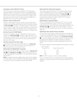
Connections to a Non-A-BUS/READY Product The ABH 4 may also be used to bring the benefits of A-BUS technology to audio systems that are not A-BUS/READY. To do this, a few additional steps are required to connect an audio feed and to install any required infrared emitters that are used to control the source equipment. Although this installation is relatively simple, you may wish to have it completed by a trained installer who is familiar with A-BUS and audio/video systems integration. Step One: Connect an Audio Source Connect the audio outputs of the source that will be used to feed the A-BUS modules by using a standard audio interconnect cable (not included) connecting the Audio Inputs £ on the ABH 4 to the audio outputs of the source device. The source may be the tape outputs of a stereo preamplifier or receiver, the tape outputs or multiroom outputs of an audio/video receiver or surround processor, or it may be a direct connection to a single source such as a CD player or tuner. Step Two: Connect the A-BUS Modules Connect the RJ-45 jacks on the Cat. 5 cabling that runs to the remote room modules to the A-BUS Outputs • on the ABH 4. Make certain that the connector is wired in accordance with the standard TIA 568A color-coding. Connect the A-BUS modules in the remote rooms to the cable in accordance with the instructions for the module. Step Three: Connect the AC Power Supply Connect the AC Power Supply furnished with the ABH 4 to the Power Input ™. Plug the AC power cord into the socket on the Power Supply. Do not connect the power cord to an AC outlet at this time. Optional Step Four: Multiple ABH 4 Connections If you are using more than one ABH 4 in a system, connect the Expansion Out Jack ∞ to the Expansion In Jack ¢ on another ABH 4, using the RJ-45 jumper cable supplied with the second ABH 4. Then, follow steps two and three as shown above. NOTE: The following steps provide additional options that extend the flexibility of your A-BUS system. If you are not familiar with audio/video systems installations, you may wish to have them completed by a properly trained installer. Optional Step Five: Status Power Connection If your system requires that the remote A-BUS models are active and able to receive commands when the host receiver, processor or preamplifier is not turned on, connect an optional power supply to the Status Input ¡. The power supply is the small type typically used to power portable electronics products and should provide a nominal 12 volts DC at 200 mA, using a standard 2.1 plug with "Center Positive". Optional Step Six: Connect IR Emitters If you are not using direct IR control connections to "IR In" jacks on products by Harman Kardon and wish to control a receiver, processor or preamp, or a source product such as a CD or DVD player, connect optional IR emitters to the IR Emitter Jacks ¶ and then place them over the IR sensor on the front panel of the unit to be controlled in accordance with the emitter manufacturer's instructions. Optional Step Seven: Remote IR Sensor Connection If the source and control equipment is behind cabinet doors or dark glass and you wish to have an optional IR sensor in the main listening room control those products, connect that sensor (not included) to the Local IR Input Terminals §. To make the installation easier, the black connector block may be removed by grasping the top and bottom of the block and pulling it out toward you. Reinstall it after the connections are made by simply pushing it back into the socket. When using an optional IR receiver (not supplied) the connections are as follows: ABH 4 "Local IR" Connection Point Sensor Connection Point V+ +12V SIG IR OUT GND GND NOTE: The STAT connection is not used in standard installations. If you are not familiar with the use of external IR sensors in systems integration applications, we strongly recommend that a trained custom installer perform the installation. 5
-
 1
1 -
 2
2 -
 3
3 -
 4
4 -
 5
5 -
 6
6 -
 7
7 -
 8
8 -
 9
9
 |
 |
