Harman Kardon AVR 135 Owners Manual - Page 7
Rear-panel Connections - codes
 |
View all Harman Kardon AVR 135 manuals
Add to My Manuals
Save this manual to your list of manuals |
Page 7 highlights
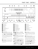
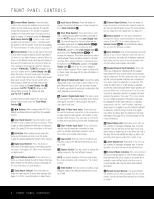
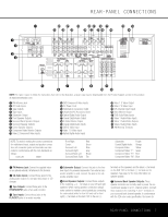
¡ ™ £ ¢ REAR-PANEL CONNECTIONS 31 jh f db · ‡ fi‹ kig e c a° fl › 135 (100W, 1A MAX) (50W, 0.5A MAX) ∞ ¶ ª ⁄ § • ,¤ NOTE: To make it easier to follow the instructions that refer to this illustration, a larger copy may be downloaded from the Product Support section for this product at www.harmankardon.com. ¡ FM Antenna Jack ™ CD Audio Inputs £ Tape Outputs ¢ Tape Inputs ∞ Subwoofer Output § Front Speaker Outputs ¶ Surround Back Speaker Outputs • Surround Speaker Outputs ª Center Speaker Outputs , Component Video Monitor Outputs ⁄ Video 2 Component Video Inputs ¤ DVD Component Video Inputs ‹ AC Power Cord › Switched AC Accessory Outlet fi Unswitched AC Accessory Outlet fl Optical Digital Audio Output ‡ Coaxial Digital Audio Output ° S-Video Monitor Output · Coaxial Digital Audio Inputs a DVD S-Video Input b Video 1 S-Video Input c Optical Digital Audio Inputs 49 47 45 43 48 46 44 42 35 37 39 41 34 36 38 40 33 26 25 37 32 27 24 36 31 28 23 35 30 29 22 34 29 30 21 33 28 31 20 32 d Video 1 S-Video Output e Video 2 S-Video Input f 6/8-Channel Direct Inputs g37 V4id1eo4M7on5it1or Output h36 35 D34V09D A4465udio45/09Video Inputs i34 V3id8eo414 A4u8dio/Video Inputs j33 Video413 Audio/Video Outputs k32 Video42 Audio/Video Inputs 31 AM Antenna Terminals NOTE: To assist in making the correct connections for multichannel input, output and speaker connec- tions, all connection jacks and terminals are color- coded in conformance with the CEA standards as follows: Front Left: White Front Right: Center: Surround Left: Surround Right: Surround Back Left: Surround Back Right: Red Green Blue Gray Brown Tan Subwoofer: Purple Coaxial Digital Audio: Orange Composite Video: Yellow Component Video "Y": Green Component Video "Pr": Red Component Video "Pb": Blue ¡ FM Antenna Jack: Connect the supplied indoor (or an optional external) FM antenna to this terminal. ™ CD Audio Inputs: Connect these jacks to the analog audio output of a compact disc player or CD changer. £ Tape Outputs: Connect these jacks to the RECORD/INPUT jacks of an audio recorder. ¢ Tape Inputs: Connect these jacks to the PLAY/OUT jacks of an audio recorder. ∞ Subwoofer Output: Connect this jack to the linelevel input of a powered subwoofer. If an external subwoofer amplifier is used, connect this jack to the subwoofer amplifier input. § Front Speaker Outputs: Connect these outputs to the matching + or - terminals on your left and right speakers. When making speaker connections always make certain to maintain correct polarity by connecting the color-coded (white for front left and red for front right) (+) terminals on the AVR 135 to the red (+) terminals on the speakers and the black (-) terminals on the AVR 135 to the black (-) terminals on the speakers. See page 12 for more information on speaker polarity. ¶ Surround Back Speaker Outputs: These speaker terminals are normally used to power the surround back speaker in a 6.1-channel system. Connect these outputs to the matching + and - terminals on your surround back channel speaker. In conformance with the CEA color-code specification, the brown ter- REAR-PANEL CONNECTIONS 7
-
 1
1 -
 2
2 -
 3
3 -
 4
4 -
 5
5 -
 6
6 -
 7
7 -
 8
8 -
 9
9 -
 10
10 -
 11
11 -
 12
12 -
13
-
14
-
15
-
16
-
17
-
18
-
19
-
20
-
21
-
22
-
23
-
24
-
25
-
26
-
27
-
28
-
29
-
30
-
31
-
32
-
33
-
34
-
35
-
36
-
37
-
38
-
39
-
40
-
41
-
42
-
43
-
44
-
45
-
46
-
47
-
48
 |
 |
