Harman Kardon AVR75 Owners Manual - Page 15
Installation and Setup
 |
View all Harman Kardon AVR75 manuals
Add to My Manuals
Save this manual to your list of manuals |
Page 15 highlights
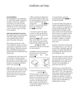
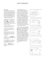
Installation and Setup 13 System Installation After unpacking the unit, and placing it on a solid surface capable of supporting its weight, you will need to make the connections to your audio and video equipment. These steps need to be done only when the receiver is first installed, or when a change is made to the input source equipment. Audio Input and Output Connections We recommend that you use high-quality cables when making connections to source equipment and recorders to preserve the quality of the signals. When making connections to audio source equipment or speakers it is always a good practice to unplug the unit from the AC wall plug. This prevents any possibility of accidentally sending audio or transient signals to the speakers that may damage them. 1. For playback only audio sources, such as a CD player, CD changer, external phono preamp or external digital to analog converter, connect the output jacks of the player to the appropriately labeled inputs on the rear panel •. 2. When connecting recording devices such as audio cassette recorders, open reel audio tape decks, DCC, DAT or MD, connect the PLAY/OUT jacks of the recorder to the Tape In jacks ¢ § on the AVR75. Connect the RECORD/IN jacks on the recorder to the Tape Out jacks £ ∞ on the AVR75. 3. Connect the output of any digital sources to be used to the appropriate connections on the AVR75 rear panel. Note that the Optical and Coaxial digital inputs °· may be used with either a Dolby Digital (AC-3) source or the output of a conventional CD or LV player's PCM (SP/DIF) output. The AC-3 RF input a may ONLY be connected to the special AC-3 RF output of a laser disc player. 4. Assemble the AM Loop Antenna supplied with the unit as shown below. Connect it to the AM and GND screw terminals ¡. NOTE: When the source device has both fixed and variable audio outputs it is best to use the fixed output unless you find that the input to the receiver is so low that the sound is noisy, or high that the signal is distorted. 5. Connect an FM antenna to the FM (75 ohm) connection ™. The FM antenna may be an external roof antenna, an inside powered or wire lead antenna, or a connection from a cable TV system. Note that if the antenna or connection uses 300-ohm twin lead cable, you must use the 300-ohm to 75-ohm adapter supplied with the unit to make the connection. 6. Connect the front, center and surround speaker outputs ¤‹› to the respective speakers. To assure that all the audio signals are carried to your speakers without loss of clarity or resolution, we suggest that you use high-quality speaker cable. Many brands of cable are available, and the choice of cable may be influenced by the distance between your speakers and this receiver, the type of speakers you use, personal preferences and other factors. Your dealer or installer is a valuable resource to consult in selecting the proper cable. Regardless of the brand of cable selected, we recommend that you use a cable constructed of fine, multistrand copper with a gauge of 14 or larger. Remember that in specifying cable, the lower the number, the thicker the cable. Cable with a gauge of 16 may be used for short runs of less than ten feet. We do not recommend that you use cables with an AWG equivalent of 18 or higher due to the power loss and degradation in performance that will occur. Cables that are run inside walls should have the appropriate markings to indicate listing with UL, CSA or other appropriate testing agency standards. Questions about running cables inside walls should be referred to your installer or a licensed electrical contractor who is familiar with the NEC and/or the applicable local building codes in your area.
-
 1
1 -
2
-
3
-
4
-
5
-
6
-
7
-
8
-
9
-
 10
10 -
 11
11 -
 12
12 -
 13
13 -
 14
14 -
 15
15 -
 16
16 -
 17
17 -
 18
18 -
 19
19 -
 20
20 -
21
-
22
-
23
-
24
-
25
-
26
-
27
-
28
-
29
-
30
-
31
-
32
-
33
-
34
-
35
-
36
 |
 |
