Harman Kardon CP 15 Quick Start Guide - Page 3
AM Antenna, FM Antenna
 |
View all Harman Kardon CP 15 manuals
Add to My Manuals
Save this manual to your list of manuals |
Page 3 highlights
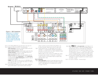
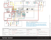
FM Antenna AM Antenna 240 135 (100W, 1A MAX) Figure 4 - DVD Connections Dotted lines indicate a connection where more than one option is available. You may use standard composite video, S-video or component video, but you do not need to use more than one video type. (50W, 0.5A MAX) Step 4. Connect AM and FM antennas (as shown above). (See page 12.) Step 5. Connect the DVD 22 to the AVR 135 as shown above: AUDIO connections: Connect the L/R Audio Out jacks on the DVD to the L/R DVD Audio in jacks on the AVR. DIGITAL AUDIO connections: Use the enclosed coaxial interconnect (orange connectors) to connect the Coaxial Digital Output on the DVD to the Coaxial Digital 1 Input on the AVR. VIDEO connections: Depending on the input available on your TV, use either composite video (dotted yellow), S-video (dotted black) or component video (dotted red/blue/green) connections. Only one connection type is needed. POWER: Plug the DVD's AC power cord into the SWITCHED output on the back of the AVR. Press the Main Power Switch on the DVD so that it is ON (see pages 13, 14-15). Step 6. Connect other source devices such as a VCR, Cable or Satellite settop box, HDTV receiver or audio recorder using the connections shown in the Device Connection Options chart and Figure 5 on the back of this Guide. Plug all sources into an AC power outlet. Step 7. Connect the AVR to your TV or video display. You must make a composite, "S" or component video connection corresponding to each video source device used in your system. Remember to switch the TV to the correct input for each source. NOTE: The AVR's on-screen menus are not available when viewing a component video connection. For that reason, a composite or S-video connection is recommended, though not required, when component video is used. Basic Configuration Step 8. Select digital inputs: Use the On-Screen Input Setup menu or the front-panel Digital Select button and the arrow buttons to select an optical or coaxial digital input, for any digital source or the DVD (see pages 16 and 23). Step 9. Use TM to set output levels: Set the Balance to 12 o'clock, and the Volume to -10dB. Sit in the listening position and hold the remote in front of you at shoulder level, pointing at the AVR. Press the SPL button for 3 seconds, and release it when the LED flashes amber. Press "5" or "7" to indicate the number of speak- ers (not including the subwoofer). Hold the remote steady until the process is completed (see page 2 of the RCP 2 owner's manual). Step 10. If you are using a component video connection to a digital television, set the DVD 22's output to Progressive Scan, as shown on page 20 of the DVD 22 manual. Step 11. Your system is configured - sit back and enjoy! SPEAKER AND DVD CONNECTIONS
-
 1
1 -
 2
2 -
 3
3 -
 4
4
 |
 |
